EN UG-020 Link 6 user guide r1.0 32
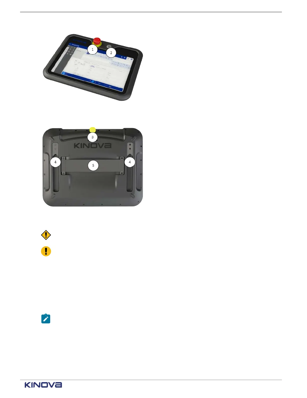
E-stop button1
Use the E-stop button to stop the robot in
emergency situations.
Power button
Figure 27: Teach pendant front
2
Use the power button to turn on the teach pendant
and access KortexWebApp.
Pendant enabling device
3
Press and hold the pendant enabling device in
the middle position when you are using the Jog
interface to manually move the robot or when you
are running a program in Hold-to-Run mode.
Mounting interface4
Align the mounting interface with the mounting
hooks and slide the pendant on the mount.
Strap holding interface
Figure 28: Teach pendant back
5
Slide your hand underneath the strap such that
your thumb rests on top of the strap.
CAUTION: Store all disconnected teach pendants in a safe location out of sight to prevent
confusion between active and inactive emergency stops.
Attention: Never disconnect the cable from the teach pendant when the controller is
switched on.
Related topics
Installing the teach pendant mount on page 118
Industrial I/O panel overview
The controller provides general-purpose electrical inputs and outputs from the Industrial I/O
panel. It also provides safety-related electrical inputs and outputs from the I/O panel.
Note: Unless otherwise specified, all voltages and currents are direct current (DC).
The I/O panel is made of two parts.
The safety I/Os are always powered by the internal power supply. The safety I/Os are divided into
two banks, bank A and bank B, for redundancy. Each bank consists of eight (8) digital inputs and
eight (8) digital outputs. The safety I/Os also contain the connections for an Emergency stop
button.
+1 514-277-3777 kinovarobotics.com
© 2022 Kinova inc. All rights reserved.