EN UG-020 Link 6 user guide r1.0 60
Reset conditions - Manual All conditions must be met.
• All the channels of the safety input that are configured for
Protective Stop with Manual Reset.
• All the channels of the safety input that are configured for
Protective Stop Reset signals the controller.
Reset result The program resumes operation.
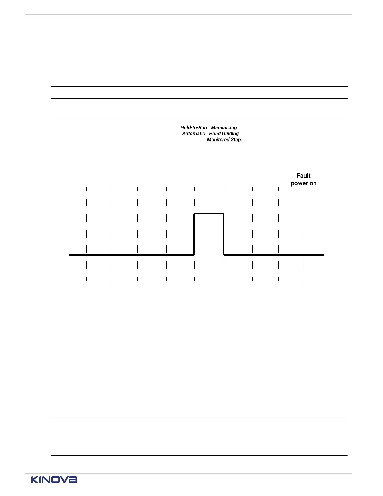
Failsafe SF02 can experience processing errors. In this case, stop category 0
is deployed.
Figure 43: Timeline for SF02 before and after being triggered
SF03 Joint position monitoring timeline
Each safety function enters one of two states during operations; it depends on the current state
of the arm and the current mode of operation.
Equally important in knowing the timeline of a safety function is knowing where to find the
current safety function status. For the status of SF03 Joint position monitoring function, there are
a few places in KortexWebApp.
• Diagnostics > Status > Safety Functions
• Diagnostics > Safety > Joint Limits > Position Limits
Table 41: SF03 trigger and action timeline
Monitor frequency of trigger 0.01 s
Trigger One of the joint positions is outside the configured limit.
Trigger results
• Stop category 2 is deployed.
• The arm is in the state Fault power on.
+1 514-277-3777 kinovarobotics.com
© 2022 Kinova inc. All rights reserved.
 Loading...