EN UG-020 Link 6 user guide r1.0 79
Important: Make sure the arm is in the Idle state before you configure safety inputs and
safety outputs. The arm is in the Idle state when the arm is switched off, but the controller
is switched on.
Each input safety function is connected to two electrical inputs. When a safety function is
triggered, the state changes on both electrical inputs simultaneously.
Likewise, each output safety function is connected to two electrical outputs. When a safety
function is triggered, the state changes on both electrical outputs simultaneously.
A discrepancy in states between the two channels implies there is an electrical system fault or
there is a device fault.
Safety inputs
Each input safety function can be assigned through KortexWebApp to one of eight channels.
When a channel is assigned to a safety input, that safety input is no longer available on the other
channels.
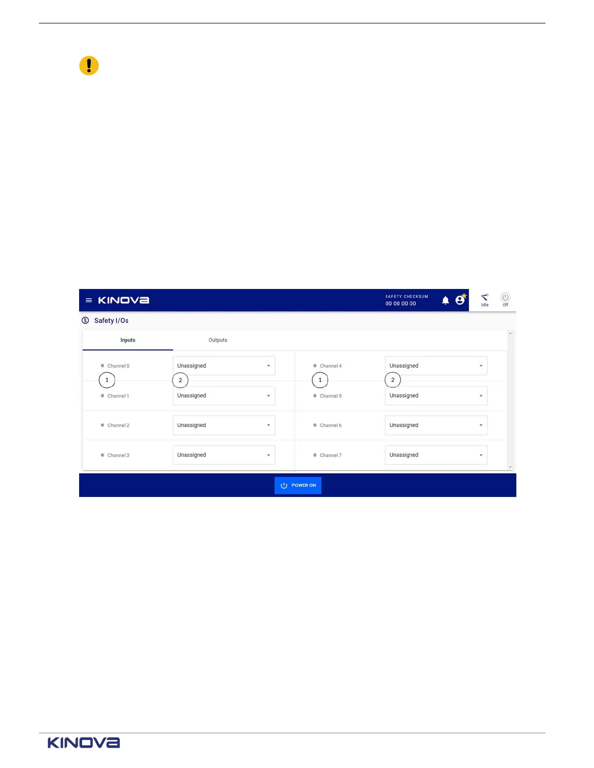
Access the Safety I/Os page by tapping Safety > Safety I/Os. The default pane is Inputs.
Figure 62: Safety inputs pane
1 Input channel 2 Safety behavior
The safety input behavior drop-down has several choices. Each safety input monitors a specific
condition. The different conditions are listed in the safety input drop-down.
+1 514-277-3777 kinovarobotics.com
© 2022 Kinova inc. All rights reserved.