EN UG-020 Link 6 user guide r1.0 37
Under normal operation, channels are not isolated from each other.
There is a monitoring point and a binary state of a visual indicator although there is no actual
hardware visual indicator.
The delay time for transitions between 0 and 1 and 1 and 0 depends on the load and on software
delays.
Table 21: Digital outputs
Digital outputs Min Typical Max Unit Note
high side
mode:
500
mARated current
push-pull
mode:
300
mA
Voltage drop V At maximum current
Leakage current mA For low state
Type Positive logic, current sourcing
Each output can drain up to a maximum of 500 mA. If many outputs are connected and are high,
the maximum current available from the internal power supply could be exceeded; an external
power supply must be used.
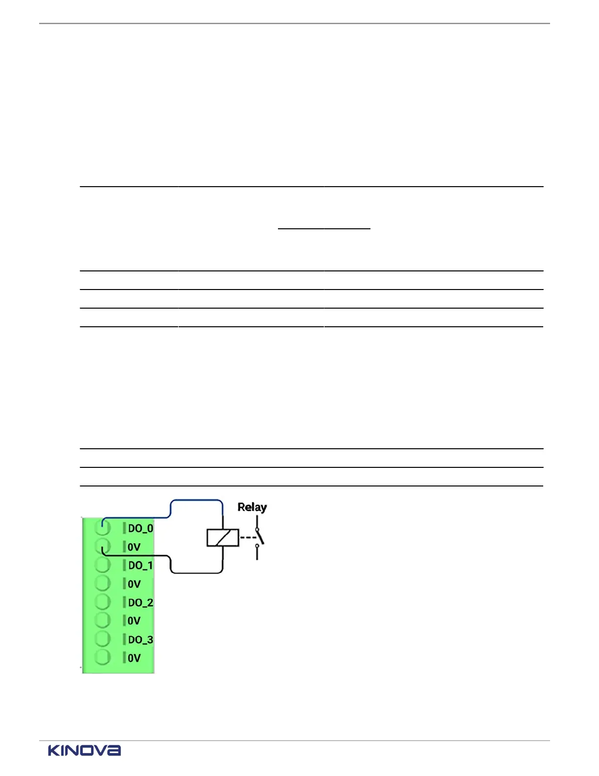
The terminal connections belong to the GENERAL PURPOSE terminal group.
Table 22: Digital output terminal connections
Label Purpose
DO_n (n=[0-7]) Terminal points for digital output
0V 0 V input to supply the digital I/Os
Figure 33: Digital output terminal connections
+1 514-277-3777 kinovarobotics.com
© 2022 Kinova inc. All rights reserved.