SETUP – Configuring Monitor Parameters
5867B_002-626e-04.16 Page 31
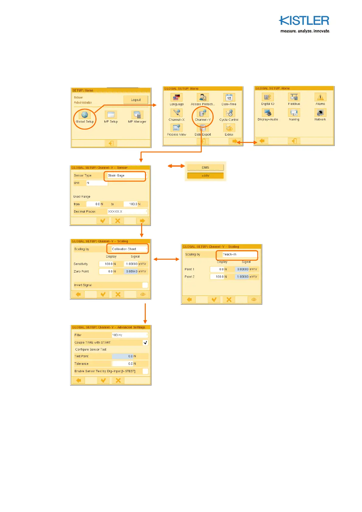
4.3.4.4 Configuring Channel Y GLOBALLY (strain gage version)
See Section 4.3.4.1 on page 28 for condition for using the parameters GLOBALLY.
Filter: 4th order low-pass filter enabling elimination of ripple on the Y channel.
Couple TARE with START: When START condition is met, for example when the START-threshold-X or
Input I-START 0-->1 is reached, the Y channel is automatically tared (duration < 0,1ms)
Test Point: Approach test position and teach. Approach this point cyclically in the process and use a
control signal (PLC) or button (on the Service menu) to check compliance.
Tolerance: Permitted variation () in the test point
Sensor Type: Strain gage or 10 V transmitter
Unit: Any unit can be entered on the keyboard
Used Range: Enter limits of range
Decimal places: Choose an expedient position for the decimal point
Scaling by "Teach-In": Here two physical quantities (such as
forces) are applied and taught one after the other. Use this
approach if there are unknown relationships between
introduced measurand (display) and measurement signal (e.g.
with torque applied using force at a certain lever arm).
Scaling using "Calibration Certificate": Required entry of the
following data from the calibration certificate. Example Sensor
type „Strain gage“:
Sensitivity/Display: With force sensors enter the value
specified under "Nominal force".
Sensitivity/Signal: Enter the mV/V value specified under
"Nominal sensitivity".
Zero Point/Display: Enter zero (0.0).
Zero Point/Signal: It is advisable to teach this mV/V value, as
zero points of strain gage sensors creep with age (even in the
original packaging!). They then no longer match the value
specified on the calibration certificate under "Zero signal".
Important: Relieve sensor of load during Teach-in!
o
 Loading...