maXYmos BL, Type 5867B…
Page 32 5867B_002-626e-04.16
Enable Test Sensor using Dig-Input: Test Sensor s enabled or disabled by means of Dig-In. Disable if, for
example, a test is to be triggered for channel X only (there is only one I-STEST input).
⇒ See page 81 for MP-specific configuration of channel Y
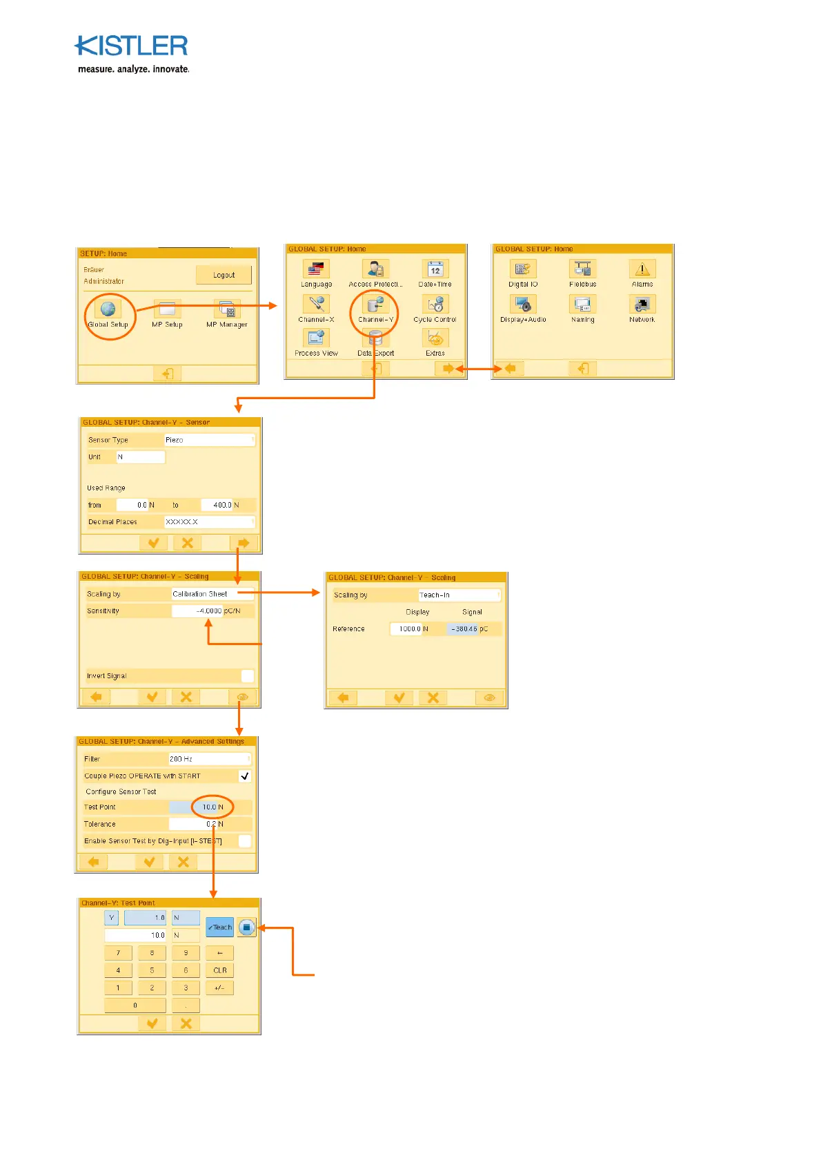
4.3.4.5 Configuring Channel Y GLOBALLY (piezoelectric version)
See Section 4.3.4.1, page 28 for condition for using the parameters GLOBALLY.
Sensor Type: This is predetermined by the version of the monitor
Unit: Enter any unit on the keyboard
Used Range: Enter expected limits of range
The parameter "up to" (400.0N) multiplied by the parameter
"sensitivity" (-4.0pC/N) gives the maximum expected quantity of
charge (-1 600pC in this case).
Do not enter an unnecessarily high value under "up to".
Decimal places: Choose an expedient position for the decimal point
Filter: 4th order low-pass filter allowing elimination of
problematic ripple. Approach appropriate value of the filter
incrementally!
Couple Piezo-OPERATE with START: If the check mark has
been placed, reset OPERATE handling is coupled to the
Start/Stop cycle. It is now permanently coupled to the START
condition (START=True-->OPERATE, START=False-->RESET (or
/OPERATE). (see p. 117 ff.)
Test Point: Approach test position mechanically and teach after
clicking blue field. This point can be approached in the process
and checked by means of a control signal (PLC) or button (on
the Service menu).
Tolerance: Permitted variation () in the test point
Enable Test Sensor using Dig-Input: Tick if Test Sensor is to be
enabled for channel X only using Dig-In.
The Teach-In a
roach is
helpful if you, for instance,
wish to perform indirect force
measurements using
piezoelectr. elongation sensors
on a C-frame. This approach
lets you enter the force value
(reference) and teach in the
associated quantity of charge.
or
Specification
on
calibration
certificat
 Loading...