maXYmos BL, Type 5867B…
Page 78 5867B_002-626e-04.16
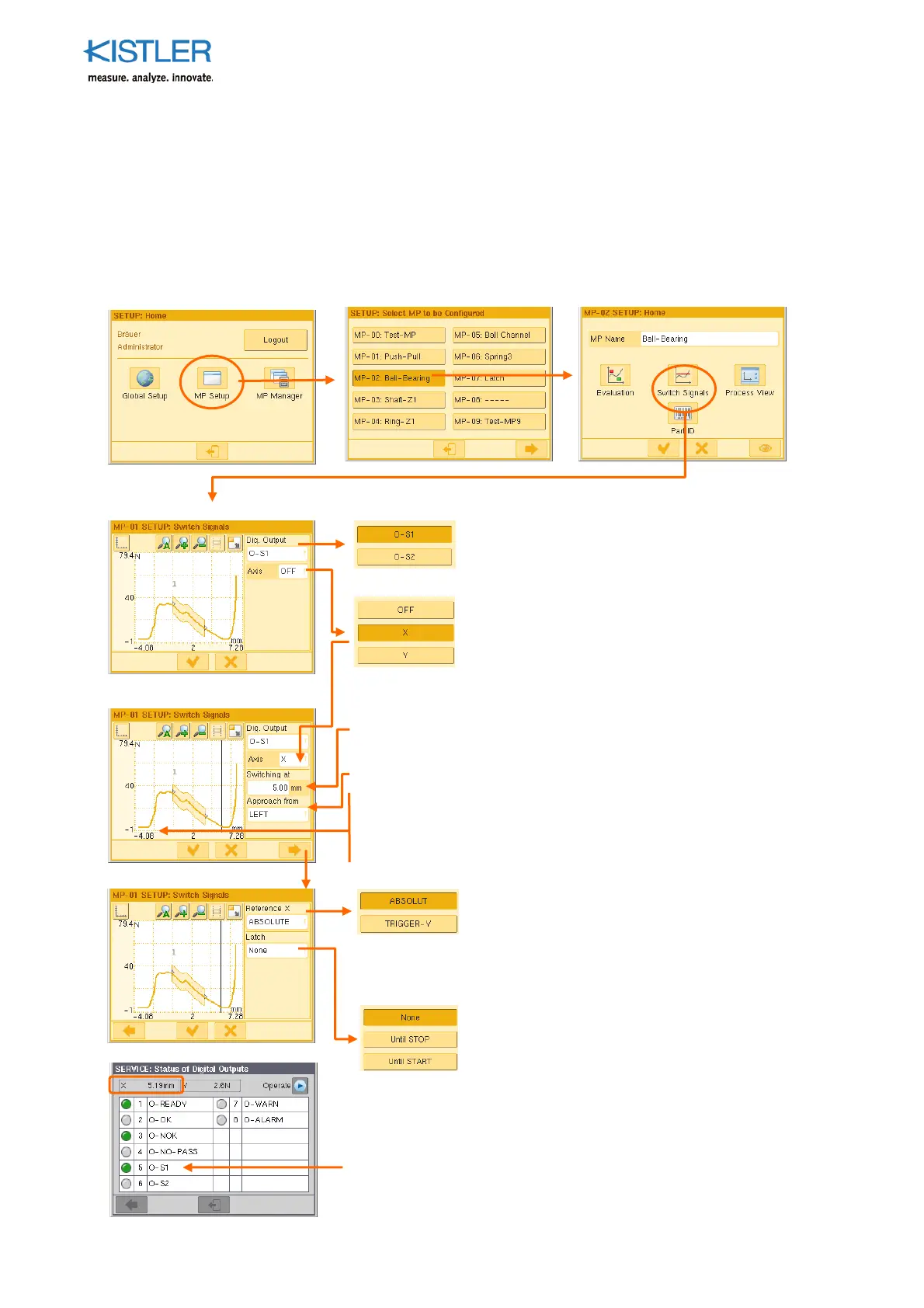
4.4.7 Configuring Switch Signals
The maXYmos has two switch signal outputs (O-S1 and O-S2), each of which can be
chosen for allocation to either channel X or channel Y. They can be used for simple control
tasks, such as switching a feed unit from "fast" to "slow".
When a freely chosen threshold is reached on the particular allocated channel, a REAL-time
signal is generated.
Choose here the out
ut to which you want
to allocate the switch signal.
Choose here the axis to which you want to
allocate the switch signal.
Note! Other than with the X(t) function, axis
= measuring channel
S
ecify the switching threshold under "Switching at".
Under "Approach from", choose the direction from which the
threshold is to be approached.
The switching threshold is dis
layed as a vertical
osition
corresponds here with the scaling of the X-axis, as both the
switching threshold and the curve (
arameter "Ref. curve on"
= ABSOLUTE (see p. 59 ff.)) are relative to ABSOLUT-X.
Under "Reference-X" s
ecify the reference
oint
for the switch signal. This now also a
lies to a
switch signal related to channel X! With
TRIGGER-Y the switching threshold is related to
the position of the trigger threshold.
Without: Out
ut changes to "1" if threshold
exceeded and returns to "0" if it is undershot
Until STOP: Output is held until STOP
Until START: Output is held until the next START
(latch = hold/lock in position)
Check the setting on the SERVICE menu → Digital Out
uts.
When the threshold is reached the allocated out
ut must
change to "1" (LED = green).
 Loading...