SETUP – Configuring Monitor Parameters
5867B_002-626e-04.16 Page 39
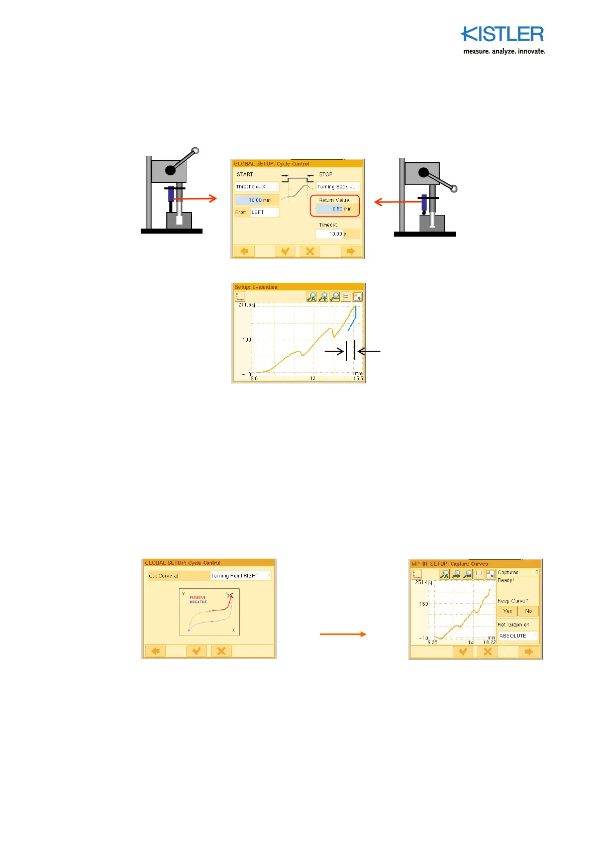
Example 2
START-STOP is again controlled by the measurand of channel X. By contrast with Example
1, the cycle is now stopped after a curve return that can be preset is reached.
In the above example, curve capture begins at 10.0 mm coming forward from the LEFT
(orange part of curve) and now ends after a return stroke of 0.5 mm (blue part of curve),
starting from the turning point RIGHT (see Section "Specifying Turning Point", page 43).
Advantage The return stroke of the press can be used for the evaluation phase, as this has
already started shortly after the turning point.
Disadvantage If the return part of the curve is relevant to quality, this method cannot be
used. In this case see Example 1!
Tip Now eliminate the returning remainder of the curve by setting "Cut Curve at"
to "Turning Point RIGHT"! See p. 44 for details!
0.50 mm (corres
onds to
"Return" parameter)
This gives a curve
(shown in the EO
Editor here) of the
following type
 Loading...