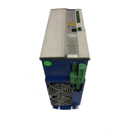
4 SERVOSTAR
®
601...620 Installation Manual
Contents 03/04 Kollmorgen
3 Interfaces
- A.4.031.1/47
3.1 Power supply .....................................................................................38
3.1.1 Mains supply connection (X0) ...................................................................38
3.1.2 24V auxiliary supply (X4).......................................................................38
3.1.3 DC-link (X7) .................................................................................38
- A.4.031.1/21,25
3.2 Motor connection with brake (X9) ......................................................................39
3.3 External regen resistor (X8) ..........................................................................39
- A.4.031.1/17,18
3.4 Feedback ........................................................................................40
3.4.1 Resolver connection (X2) ......................................................................40
- A.4.031.1/26
3.4.2 Encoder (X1) ................................................................................41
- A.4.031.1/27
3.5 Control signals, monitor signals .......................................................................42
3.5.1 Analog inputs (X3) ............................................................................42
- A.4.031.1/23
3.5.2 Analog outputs (X3)...........................................................................43
- A.031.1/22
3.5.3 Digital control inputs (X3) ......................................................................44
- A.4.031.1/24
3.5.4 Digital control outputs (X3) .....................................................................45
- A.4.031.1/20
3.6 Encoder simulations ................................................................................46
3.6.1 Incremental encoder simulation - A quad B position output (X5) ........................................46
- A.4.031.1/11
3.6.2 SSI encoder simulation - position output (X5) .......................................................47
- A.4.031.1/12
3.6.3 Interface for master-slave operation, encoder input ..................................................48
3.6.3.1 Connection to a SERVOSTAR master, 5V signal level (X5) ........................................48
- A.4.031.1/16,3/2
3.6.3.2 Connection to encoders with 24V signal level (X3) ...............................................49
3.6.3.3 Connection to a sine-cosine encoder (X1)......................................................49
- A.4.031.1/44,43
3.7 Interface for stepper-motor controls (pulse-direction) .......................................................50
- A.4.031.3/2
3.7.1 Connection to stepper-motor controller with 5V signal level (X5)........................................51
3.7.2 Connection to stepper-motor controller with 24V signal level (X3).......................................51
- A.4.031.1/10,45
3.8 RS232 interface, PC connection (X6) ...................................................................52
- A.4.031.1/13,14
3.9 CANopen Interface (X6) .............................................................................53
- A.4.031.1/15, 1/36
4Setup
4.1 Important notes ....................................................................................55
4.2 Parameter setting ..................................................................................57
4.2.1 Multi-axis systems ............................................................................57
4.2.1.1 Node address for CAN-bus .................................................................57
4.2.1.2 Baud rate for CAN-bus ....................................................................57
- A.4.031.4/37
4.2.2 Key operation / LED display ....................................................................58
4.2.2.1 Key operation............................................................................58
4.2.2.2 Status display ...........................................................................58
- A.4.031.3/4
4.2.2.3 Standard menu structure ...................................................................59
4.2.2.4 Extended menu structure...................................................................59
- A.4.031.3/3
4.3 Error messages ...................................................................................60
4.4 Warning messages .................................................................................61
5 Extensions / Accessories
5.1 Option -AS-, restart lock for personal safety ..............................................................63
5.1.1 Advantages of the -AS- option ..................................................................63
5.1.2 Functional description .........................................................................63
5.1.3 Block diagram ...............................................................................64
5.1.4 Signal diagram (sequence) .....................................................................64
- A.4.031.1/32,30
5.1.5 Installation / Setup ............................................................................65
5.1.5.1 Safety instructions ........................................................................65
5.1.5.2 Functional test ...........................................................................65
5.1.5.3 Connection diagram.......................................................................65
- A.4.031.1/30
5.1.6 Application examples .........................................................................66
5.1.6.1 Moving single axes or axis-groups in setting-up operation .........................................66
5.1.6.2 Switching off grouped axes with separate working areas ..........................................66
5.1.6.2.1 Control circuit.......................................................................66
- A.4.031.1/311
5.1.6.2.2 Mains supply circuit ..................................................................67
- A.4.031.3/05
5.2 Expansion card -I/O-14/08-...........................................................................68
5.2.1 Fitting the expansion card ......................................................................68
5.2.2 Technical data ...............................................................................68
5.2.3 Light emitting diodes (LEDs) ....................................................................68
5.2.4 Position of the connectors ......................................................................69
- A.4.031.4/42
5.2.5 Connector assignments........................................................................70
5.2.6 Select motion task number (Sample) .............................................................70
5.2.7 Connection diagram ..........................................................................71
- A.4.012.4/33
Drawing Page

 Loading...