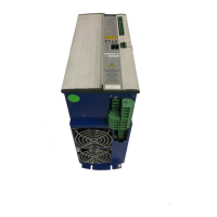
SERVOSTAR
®
601...620 Installation Manual 5
Kollmorgen 03/04 Contents
5.3 Expansion card -PROFIBUS- .........................................................................72
5.3.1 Position of the connectors ......................................................................72
5.3.2 Fitting the expansion card ......................................................................72
- A.031.4/62
5.3.3 Connection technology ........................................................................73
5.3.4 Connection diagram ..........................................................................73
- A.4.031.1/41
5.4 Expansion card -SERCOS-...........................................................................74
5.4.1 Position of the connectors ......................................................................74
5.4.2 Fitting the expansion card ......................................................................74
- A.4.031.4/69
5.4.3 Light emitting diodes (LEDs) ....................................................................75
5.4.4 Connection technology ........................................................................75
5.4.5 Connection diagram ..........................................................................75
- A.4.037.4/02
5.5 Expansion card -DeviceNet- ..........................................................................76
5.5.1 Position of the connectors ......................................................................76
5.5.2 Fitting the expansion card ......................................................................76
- A.031.4/62
5.5.3 Connection technology ........................................................................77
5.5.4 Connection diagram ..........................................................................77
5.5.5 Combined Module/Network Status LED ...........................................................77
- A.4.031.1/56
5.6 Expansion card- ETHERNET - ........................................................................78
5.6.1 Fitting the expansion card ......................................................................78
5.6.2 Connectors .................................................................................78
5.6.3 LEDs ......................................................................................78
5.6.4 Position of the connectors ......................................................................79
5.6.5 Connection diagram ..........................................................................79
- A.4.045.4/14, 4/15
5.7 Expansion card for Single Axis Controller -SAC- ..........................................................80
5.7.1 Fitting the expansion card ......................................................................80
5.7.2 Technical data ...............................................................................80
5.7.3 Position of the connectors ......................................................................81
5.7.4 Connector assignments........................................................................81
5.7.4.1 RS-232 communication X17 (SubD 9-pin, plug) .................................................81
- A.4.045.4/10, 31.1/60
5.7.4.2 RS-485 communication X17 (SubD 9-pin, plug) .................................................82
5.7.4.3 DeviceNet communication X16 (Phönix, 5-pin) ..................................................82
- A.4.031.1/58,61, 45.1/28
5.7.4.4 Digital inputs/outputs, connector X18 (SubD 26-pin, socket) .......................................83
5.8 Expansion module -2CAN- ...........................................................................84
5.8.1 Position of the connectors ......................................................................84
5.8.2 Fitting the expansion module ...................................................................84
- A.4.031.4/70
5.8.3 Connection technology ........................................................................85
5.8.4 Connector assignments........................................................................85
5.8.5 Connection diagram ..........................................................................85
- A.4.037.4/08
5.9 Accessories ......................................................................................86
5.9.1 External 24V DC / 5A supply ....................................................................86
- A.4.037.4/07
5.9.2 External 24V DC / 20A supply ...................................................................87
- A.4.012.4/33
5.9.3 External regen resistor BARxxx .................................................................88
- A.4.947.4/22
5.9.4 External regen resistor BAR(U)xxx ...............................................................89
- A.4.947.4/25
5.9.5 Motor choke box 3YL-20 .......................................................................90
- A.4.030.4/10
6 Appendix
6.1 Transport, storage, maintenance, disposal...............................................................91
6.2 Removing faults/warnings............................................................................92
6.3 Glossary .........................................................................................94
6.4 Order numbers ....................................................................................96
6.5 Index ............................................................................................97
Drawing Page

 Loading...