Step 4: Route the cables
35
Step 4: Route the cables
Follow these guidelines as you route specific cables through the points of entry
into the base of the InTouch. For example:
• Ethernet — Route the cable through the back wall into the base or through the
hole at the bottom of the base
• Remote readers — If you purchased a remote badge reader or universal relay
kit, you must run those cables through the wall or along the wall into the base
of the InTouch. See the installation guides for those options.
• Transformer — If you ordered a transformer with a 6-ft. cable to plug into an
external wall outlet, you will route that cable through one of the bottom access
holes after you install the transformer (“Step 5: Install components and
options in the base” on page 38.)
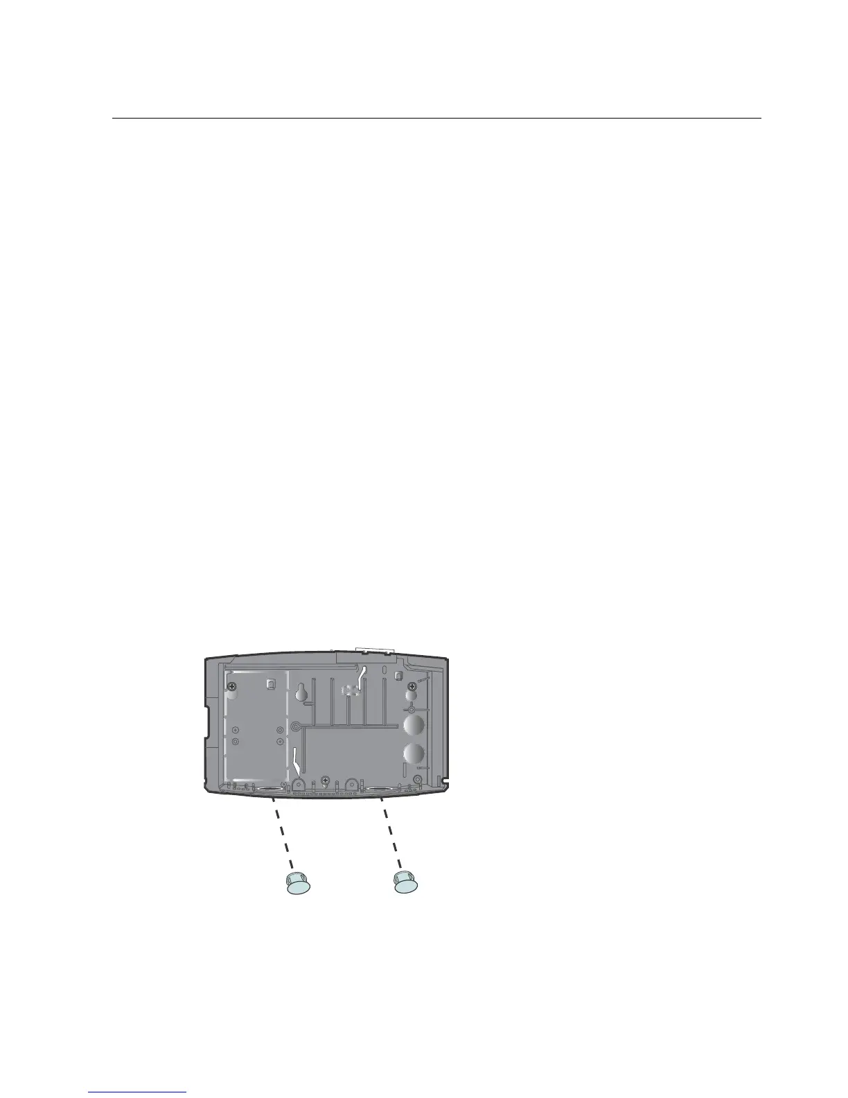
Remove cable access plugs
The base of the InTouch has two cable access holes in the top right of the base and
two holes at the bottom of the base. If you plan to route cable through one or both
bottom holes, remove the plastic plugs.