COMMON RAIL SYSTEM
07-CR-E5,07-CR-TE5,07-CR-TIE5, DM
1-S98
9Y3200007CRS0136US0
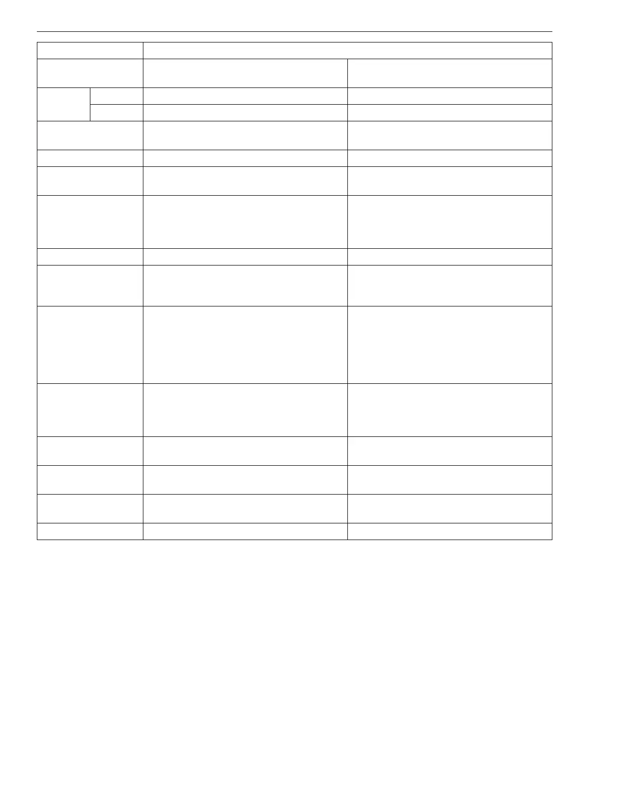
Name Sensor supply voltage 1 abnormality
ISO 14229
P-Code
P0642 P0643
J1939-73
SPN 3509 3509
FMI 43
SPN Name
SAE J1939 Table C1
Sensor supply voltage 1 Sensor supply voltage 1
DTC Name Sensor supply voltage 1: Low Sensor supply voltage 1: High
Detection item
• Sensor supply voltage 1 error or
recognition error
• Sensor supply voltage 1 error or
recognition error
DTC Set
Preconditions
• Battery voltage is normal
• Key switch turn ON
• Starter Switch signal (Engine ECU: V12
terminal) is not activated
• Battery voltage is normal
• Key switch turn ON
• Starter Switch signal (Engine ECU: V12
terminal) is not activated
DTC set parameter • Voltage to sensor is below 4.375 V • Voltage to sensor is above 5.625 V
Time to action or
number of error
detection
• Transient • Transient
Limp Home Action
by engine ECU
(system action)
• Output limitation: Approximately 50 % of
normal condition
• Speed limitation (Accelerator limitation:
50 %)
•EGR stop
• Intake throttle 100 % open
• Output limitation: Approximately 50 % of
normal condition
• Speed limitation (Accelerator limitation:
50 %)
• EGR stop
• Intake throttle 100 % open
Behaviour During
Malfunction
• Faulty starting
• Insufficient output
• Worsening exhaust gas performance
• Engine stops in some case
• Faulty starting
• Insufficient output
• Worsening exhaust gas performance
• Engine stops in some case
Engine Warning
Light
•ON •ON
Recovery from
error
• Key switch turn OFF • Key switch turn OFF
Delay time for
recovery
––
Remark • Emission related • Emission related