COMMON RAIL SYSTEM
07-CR-E5,07-CR-TE5,07-CR-TIE5, DM
1-S9
[3] CHECKING THE COMMUNICATION OPERATION OF THE
INTERFACE (DST-i)
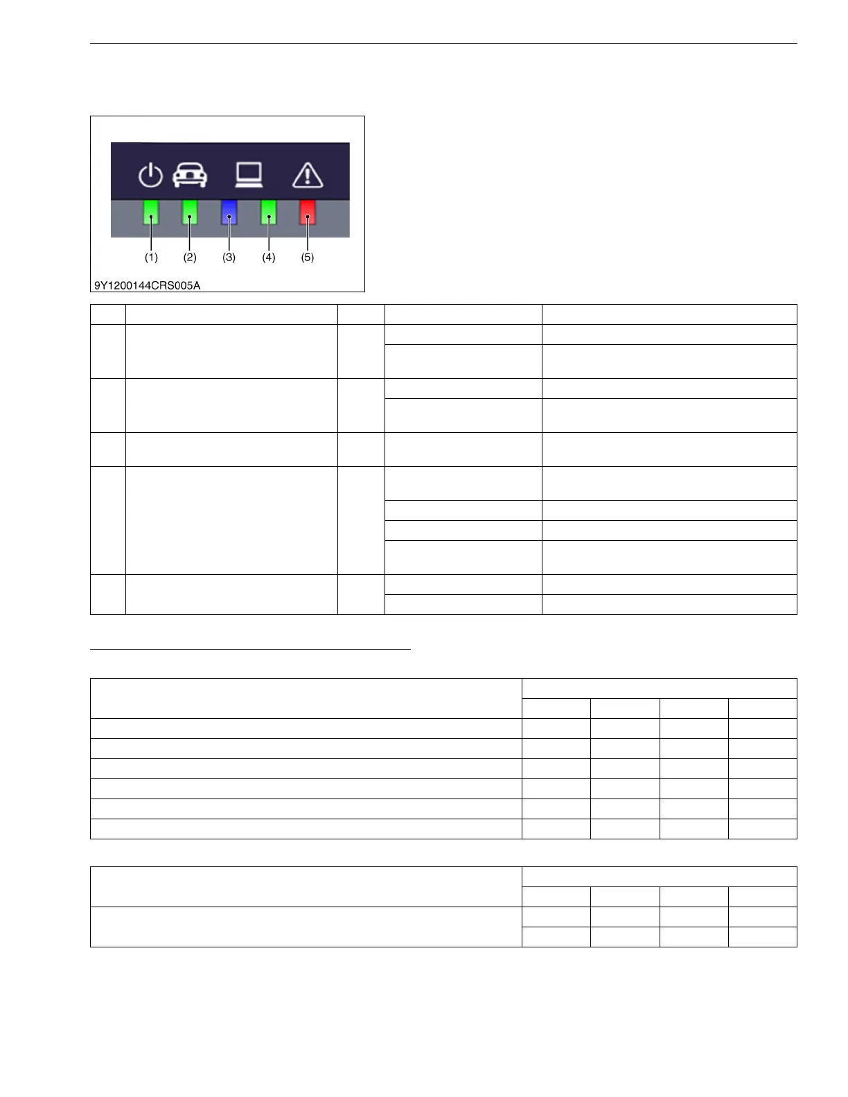
The communication operation can be checked with the
illuminating condition of the five indicators on the DST-i unit.
If a communication error occurs, check the illuminating
condition of each indicator and repair or replace the malfunction
(including cable open circuits).
9Y3200007CRS0013US0
DST-i operation Status and Display Specification
Light Operation During Normal Conditions
Light Operation During Abnormal Operation
9Y3200007CRS0014US0
(1) Power Indicator
(2) Machine Communication Indicator
(3) PC Communication (Bluetooth)
Indicator
(4) PC Communication (USB) Indicator
(5) Error Detection Indicator
No. Type of LED Color LED Status Details
(1) Power Indicator
Green
Light OFF Power OFF
Light ON
Power is supplied from machine cable or USB
cable
(2) Machine Communication Indicator
Green
Light OFF Stand-by for communication
Light Flashing (synchronized
with communication)
Communication in progress
(3) PC Communication (Bluetooth) Indicator
Blue Reserved
Bluetooth communication status
(Bluetooth is option)
(4) PC Communication (USB) Indicator
Green
Light OFF
USB cable has not connected to PC or USB
driver has not installed to PC
Light ON Stand-by for communication
Light Flashing Stand-by for establishment of communication
Light Flashing (synchronized
with communication)
Communication in progress
(5) Error Detection Indicator
Red
Light OFF Normal conditions
Light Flashing Error occurs
DST-i Status
LED Status
Power Machine USB Error
Power OFF
Power ON
USB stand-by status
USB cable has not connected to PC or USB driver has not installed to PC
Machine stand-by for communication
Machine / USB communication in progress
DST-i Status
LED Status
Power Machine USB Error
System Error
: Light OFF :Light ON : Light Flashing : Light Flashing (Synchronized
with communication)