COMMON RAIL SYSTEM
07-CR-E5,07-CR-TE5,07-CR-TIE5, DM
1-S329
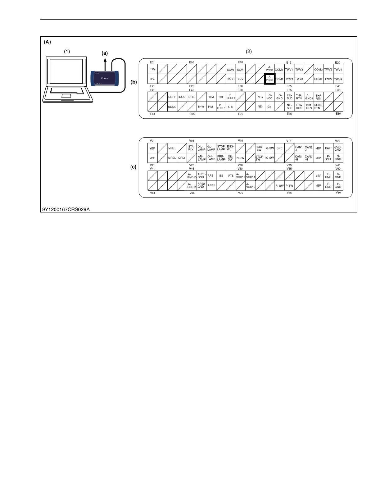
(2) Connector Connection Fault Verification Method
As per the diagram above, measure both the data monitor and connector voltage simultaneously.
Ex.) Coolant temperature sensor
a) Read in the "Coolant Temperature Output Voltage" value from the data monitor.
b) Measure the voltage directly from the corresponding engine ECU terminal.
Judge as a connector connection fault if b) is satisfactory and a) is unsatisfactory. Since some malfunctions only
occur intermittently, measure voltage while pulling and shaking the wires in order to try to get the malfunction to
reoccur.
9Y3200007CRS0532US0
(1) Diagnosis Tool Data Monitor
(Sensor Output Voltage)
(2) Voltage Measurement (A) Sensor Example (a) CAN1 Connector
(b) Engine ECU Connector 1
(Engine Side)
(c) Engine ECU Connector 2
(Machine Side)