COMMON RAIL SYSTEM
07-CR-E5,07-CR-TE5,07-CR-TIE5, DM
1-S293
(56) Exhaust Gas Temperature Sensor (T1) Emergency High (DTC P3003 /
3242-0)
Behaviour during malfunction:
• Engine stops
• Inhibit cranking until down to 300 °C (572 °F)
Detection item:
• DPF inlet temperature (T
1
) high
DTC set preconditions:
• Exhaust gas temperature sensor T
0
, T
1
and T
2
are normal
• Battery voltage is normal
DTC set parameter:
• DPF inlet temperature (T
1
): 715 °C (1319 °F) or more
Engine warning light:
•ON
Limp home action by engine ECU (system action):
• Stop injection (Q = 0 mm
3
/st)
• Engine stop
• Inhibit starter relay activation until exhaust gas temperature reduces down to 300 °C (572 °F)
Recovery from error:
• Under 300 °C (572 °F) & key switch turn OFF
9Y3200007CRS0454US0
1. Check the Air Intake System
1. Check in accordance with "6.[1] AIR INTAKE SYSTEM
INSPECTION PROCEDURE". (Refer to page 1-S320)
• If the two errors occur from "Emergency exhaust gas
temperature sensor T
0
high", "Emergency exhaust gas
temperature sensor T
1
high", and "Emergency exhaust gas
temperature T
2
high" at the same time, check the exhaust
gas temperature starting from a bigger number.
• Check the clogging condition of the air cleaner. If it is very
dirty, replace the new one.
• Check if the suction hose of the turbocharger blower does
not come off. If the hose comes off, install it.
• Check the suction path for leaks. (Suction path joints,
suction pipes, hoses)
• Check the clogging condition of the fuel filter. If it is very
dirty, replace the new one.
• Check the installation of all exhaust gas temperature
sensors (T
0
, T
1
and T
2
).
• Check the engine oil level.
• Check the engine coolant level.
9Y3200007CRS0450US0
OK Go to "2. Check the Exhaust Gas Temperature".
NG Repair in accordance with "6.[1] AIR INTAKE SYSTEM INSPECTION
PROCEDURE". (Refer to page 1-S320)
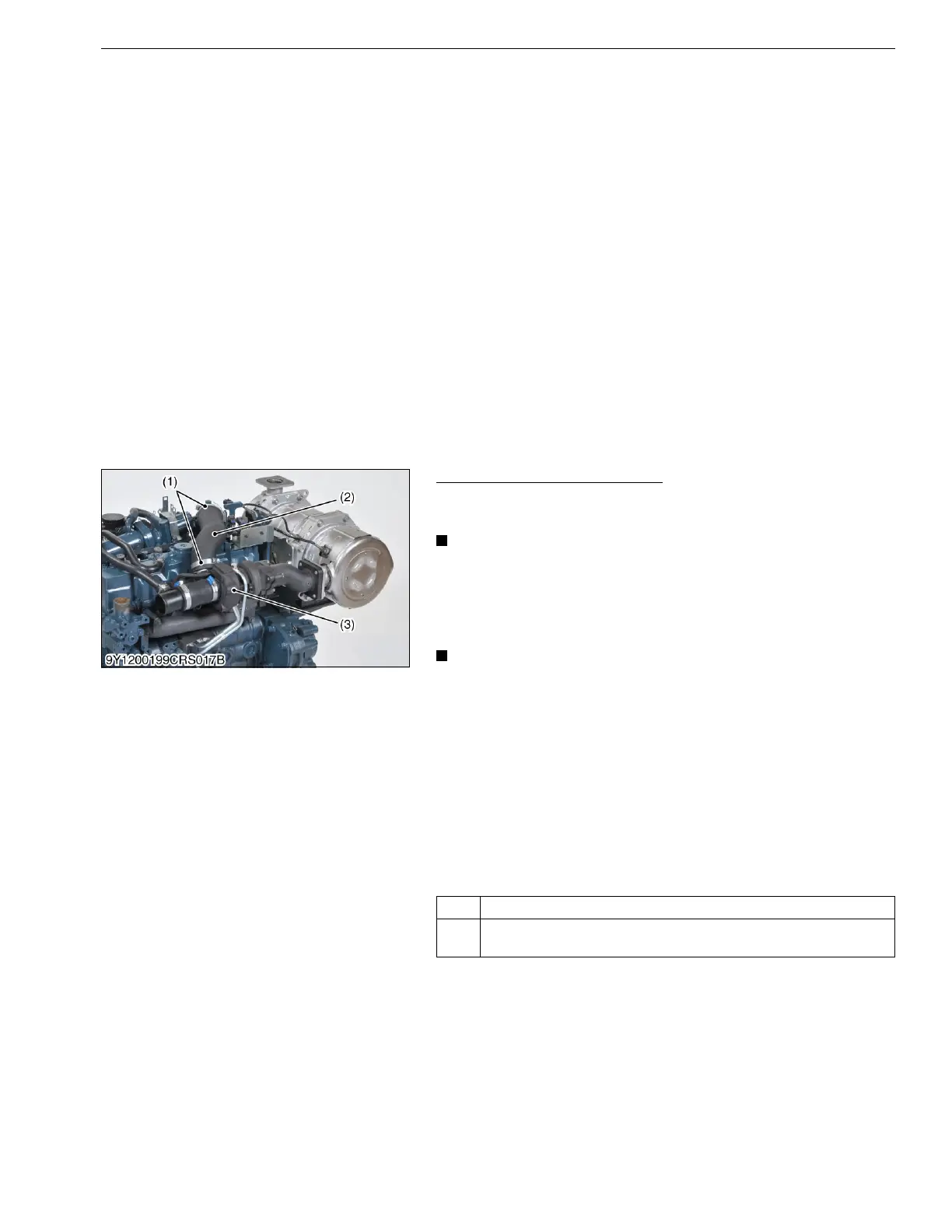
(1) Hose Clamp
(2) Hose
(3) Turbocharger