COMMON RAIL SYSTEM
07-CR-E5,07-CR-TE5,07-CR-TIE5, DM
1-S8
2. DIAGNOSTIC TOOL CONNECTION PROCEDURE
[1] DIAGNOSTIC CONNECTOR POSITIONS
1. Refer to the operator's manual for this machine to check the
position for connecting the diagnosis tool.
9Y3200007CRS0010US0
[2] DIAGNOSTIC TOOL CONNECTION PROCEDURE
• At first time usage, it is necessary to do "Communication Setting" with administrator user account.
• Prepare a PC on which the diagnostic software has already been installed.
• When connecting the diagnosis cable, ensure that the key switch on the machine side is OFF.
9Y3200007CRS0011US0
1. Start up a PC on which the diagnostic software has been
installed with administrator user account.
2. Connect the machine-side CAN1 connector (a) to the interface
connector (To Machine) (2) with the cable (To Machine) (1).
3. Connect the cable (USB) (4) to the USB connector (To PC) (3)
and then connect the USB cable to the USB port on PC.
4. Start the diagnostic software.
5. Select "Communication Setting" from "System Setting" in the
menu and execute. (Only when performing the initial settings.)
• The USB port used while the "Communication Setting"
process, should always be used.
9Y3200007CRS0012US0
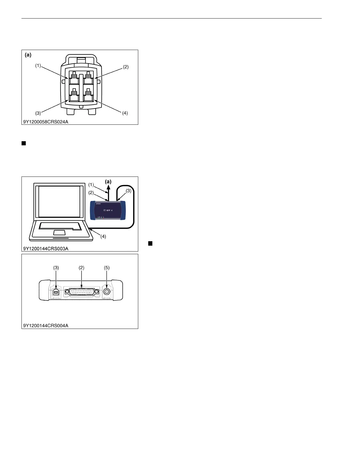
(1) Terminal IG-SW (V13, V33)
(2) Terminal CAN1-H (V36)
(3) Terminal S-GND (V60)
(4) Terminal CAN1-L (V16)
(a) CAN1 Connector
(1) Cable (To Machine)
(2) Interface Connector (To Machine)
(3) USB Connector (To PC)*
(4) Cable (USB)
(5) DC Jack (Reserved)*
(a) CAN1 Connector
* Rubber cap is attached to USB connector and DC jack each