COMMON RAIL SYSTEM
07-CR-E5,07-CR-TE5,07-CR-TIE5, DM
1-S326
[3] ELECTRIC SYSTEM INSPECTION PROCEDURE
(1) Basics Of Checking Electrical / Electronic Circuit Systems
Measure the Engine ECU Terminal Voltage and Resistance
1. When measuring the voltage and resistance of each terminal,
insert the multimeter probe into the rear side of the wiring
harness connector. If connectors are small making it difficult to
insert the probe, insert a fine metal wire into the rear of the
connector and touch the wire to the probe.
• When inserting a fine metal wire for measurement
purposes, ensure that the connector waterproof rubber is
not damaged.
9Y3200007CRS0526US0
Open Circuit Check
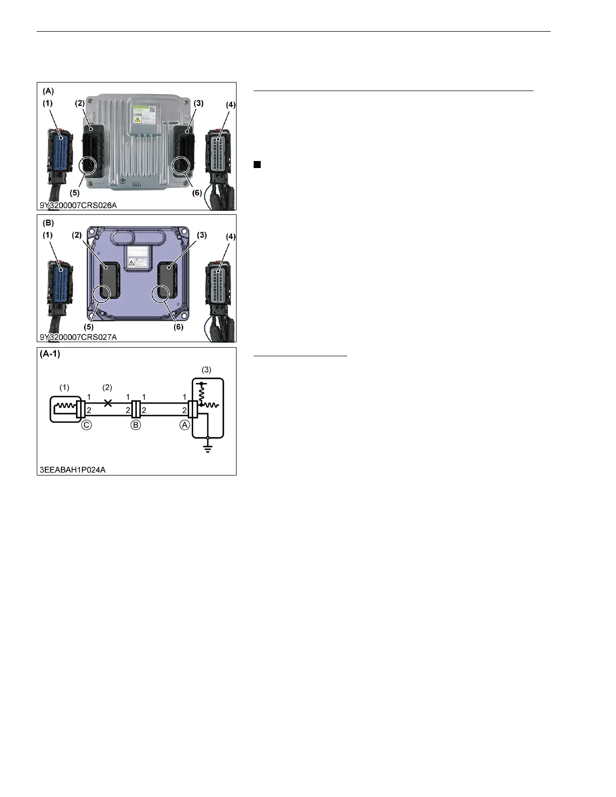
1. When dealing with a wiring harness open circuit like that
depicted in Figure A-1, check continuity or voltage to determine
the location of the open circuit.
9Y3200007CRS0527US0
(1) Engine ECU Wiring Harness
Connector 1
(Engine Side)
(2) Engine ECU Connector 1
(Engine Side)
(3) Engine ECU Connector 2
(Machine Side)
(4) Engine ECU Wiring Harness
Connector 2 (Machine Side)
(5) E01 Position
(6) V01 Position
(A) Engine ECU (Denso)
(B) Engine ECU (Kubota)
(1) Sensor
(2) Open Circuit
(3) Engine ECU