COMMON RAIL SYSTEM
07-CR-E5,07-CR-TE5,07-CR-TIE5, DM
1-S327
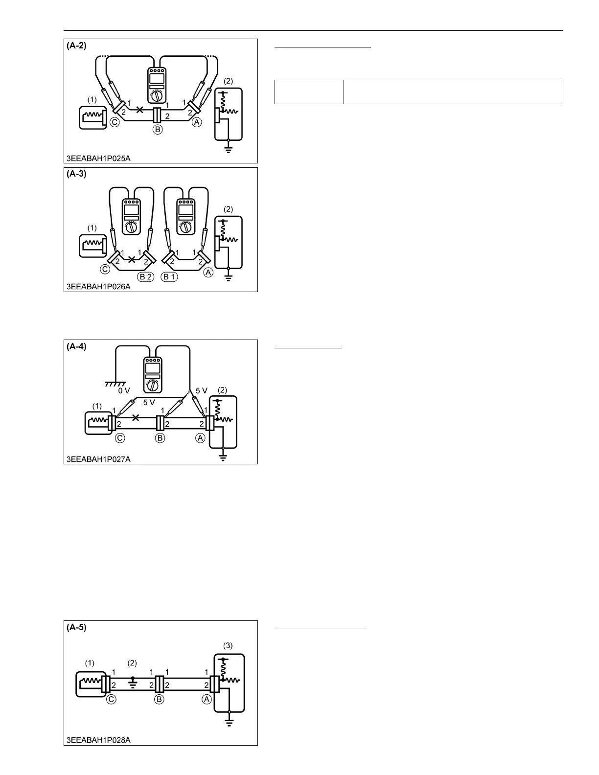
Check for Continuity
1. Remove connectors "A" and "C" and measure resistance
between the two.
(Reference)
• Measure resistance while gently shaking the wiring harness up
and down, and side-to-side.
2. In the case of Figure A-2, there is no continuity (open circuit)
between terminal 1 of connector "A" and terminal 1 of
connector "C". However, there is continuity between terminal 2
of connector "A" and terminal 2 of connector "C". As a result, it
can be said that there is an open circuit between terminal 1 of
connector "A" and terminal 1 of connector "C".
3. Remove connector "B" and measure the resistance in the
connector.
4. In the case of Figure A-3, there is continuity between terminal 1
of connector "A" and terminal 1 of connector "B1". However,
there is no continuity (open circuit) between terminal 1 of
connector "B2" and terminal 1 of connector "C". As a result, it
can be said that there is an open circuit between terminal 1 of
connector "B2" and terminal 1 of connector "C".
9Y3200007CRS0528US0
Check Voltage
1. In the case of the circuit that supplies voltage to the engine ECU
connector terminals, check for an open circuit by performing a
voltage check.
2. As depicted in Figure A-4, measure the voltage of the engine
ECU 5 V output terminal between the body ground and terminal
1 of connector "A" with all connectors connected. Next,
measure in order the voltage between terminal 1 of connector
"B" and the body ground, and terminal 1 of connector "C" and
the body ground.
3. The faulty circuit and measurement results are as per below.
(Measurement Results)
• Voltage between terminal 1 of connector "A" and the body
ground is 5 V.
• Voltage between terminal 1 of connector "B" and the body
ground is 5 V.
• Voltage between terminal 1 of connector "C" and the body
ground is 0 V.
(Faulty Circuit)
• There is an open circuit between terminal 1 of connector "B"
and terminal 1 of connector "C".
9Y3200007CRS0529US0
Short Circuit Check
1. As per Figure A-5, if there is a short in the wiring harness
ground, perform a "Ground continuity check" to determine
the source of the short.
9Y3200007CRS0530US0
Service
specification
Less than 1 Ω
(1) Sensor (2) Engine ECU
(1) Sensor (2) Engine ECU
(1) Sensor
(2) Short Circuit
(3) Engine ECU