COMMON RAIL SYSTEM
07-CR-E5,07-CR-TE5,07-CR-TIE5, DM
1-M4
[4] WIRING DIAGRAM
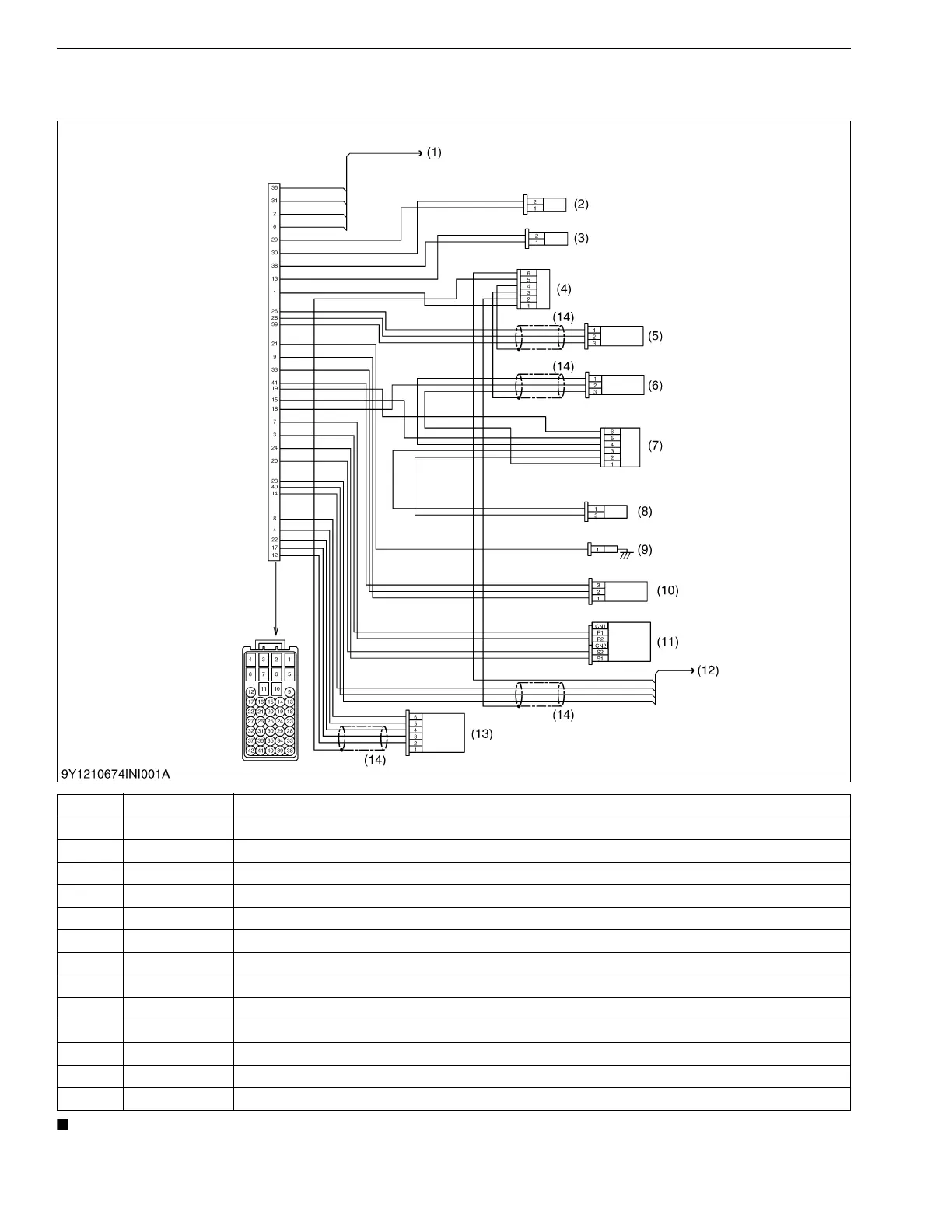
(1) Engine Intermediate Harness (Engine Side Harness)
• The picture shows the pin arrangement of the connector housing viewed from wire side, not mating side.
9Y3200007CRM0004US0
(1) − CAN and EGR
(2) CN202 Intake Air Temperature Sensor
(3) CN203 Coolant Temperature Sensor
(4) CN215 Engine Joint Connector 1
(5) CN204 Rail Pressure Sensor
(6) CN205 Crankshaft Position Sensor
(7) CN216 Engine Joint Connector 2
(8) CN206 Resistance Connector (1.1 kΩ)
(9) CN207 Oil Pressure Switch
(10) CN208 Boost Pressure Sensor
(11) CN209 / 210 Supply Pump
(12) − Camshaft Position Sensor
(13) CN212 Intake Throttle Valve
(14) − Shield Cable