COMMON RAIL SYSTEM
07-CR-E5,07-CR-TE5,07-CR-TIE5, DM
1-S202
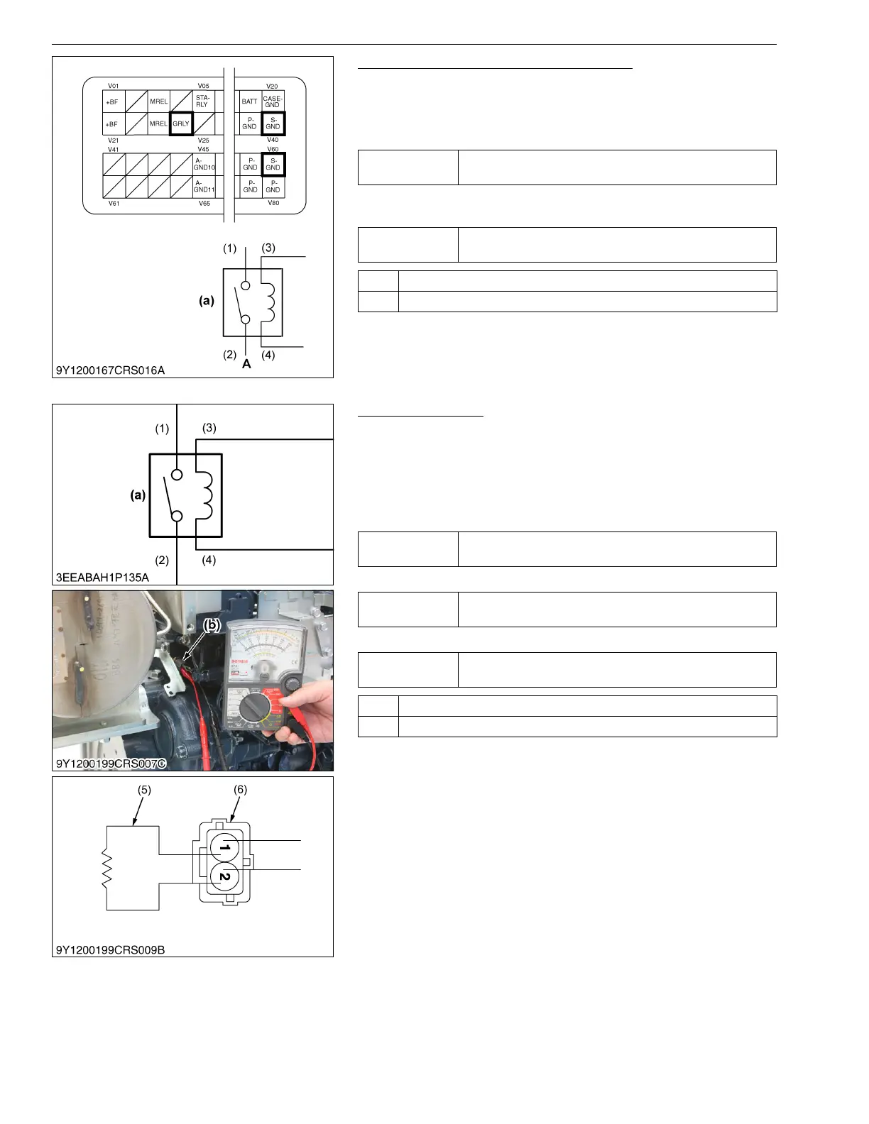
2. Check the Wiring Harness / Connector
1. Remove the connector from the engine ECU side and check the
state of the continuity between terminal V24 and (3).
2. Next, check the state of the continuity between terminal V40 /
V60 and (4).
3. Check the connector for poor connection, engagement and
contact.
9Y3200007CRS0291US0
3. Check the Relay
1. After disconnecting the connector of coolant temperature
sensor and connect the dummy resistor (5) as shown in the left
figure, and turn the key switch ON.
Dummy Resistor: 15 to 25 kΩ
[Comparable to Approx. −30 to −20 °C (Approx. −22 to −5 °F)]
2. Measure the voltage between (3) and (4).
3. Check the state of the continuity between (1) and (2).
4. Measure the resistance in the relay unit (between (3) and (4)).
9Y3200007CRS0292US0
Service
specification
Both have continuity
Service
specification
No poor connection, engagement or contact.
OK Go to "3. Check the Relay".
NG Replace the faulty areas.
(1) Terminal +B
(2) Terminal MAHR
(3) Terminal GRLY
(4) Terminal GND
(a) Air Heater (Glow) Relay
A: To Main Air Heater (Glow) Relay
Service
specification
When relay is ON: Battery voltage value
When relay is OFF: Approx. 0 V
Service
specification
When relay is ON: Continuity
When relay is OFF: No continuity
Service
specification
Coil resistance value of relay to use
OK Go to "4. Engine ECU replacement check".
NG Relay fault → Replace.
(1) Terminal +B
(2) Terminal MAHR
(3) Terminal GRLY
(4) Terminal GND
(5) Dummy Resistor
(6) Connector
(a) Air Heater (Glow) Relay
(b) Coolant Temperature Sensor
 Loading...


