COMMON RAIL SYSTEM
07-CR-E5,07-CR-TE5,07-CR-TIE5, DM
1-S210
9Y3200007CRS0307US0
1. Check the Exhaust Gas Temperature Sensor Signals
1. Place the key switch in the ON position, and check the "Exhaust
gas temperature" and "Exhaust gas temperature sensor output
voltage" on the diagnosis tool data monitor.
9Y3200007CRS0308US0
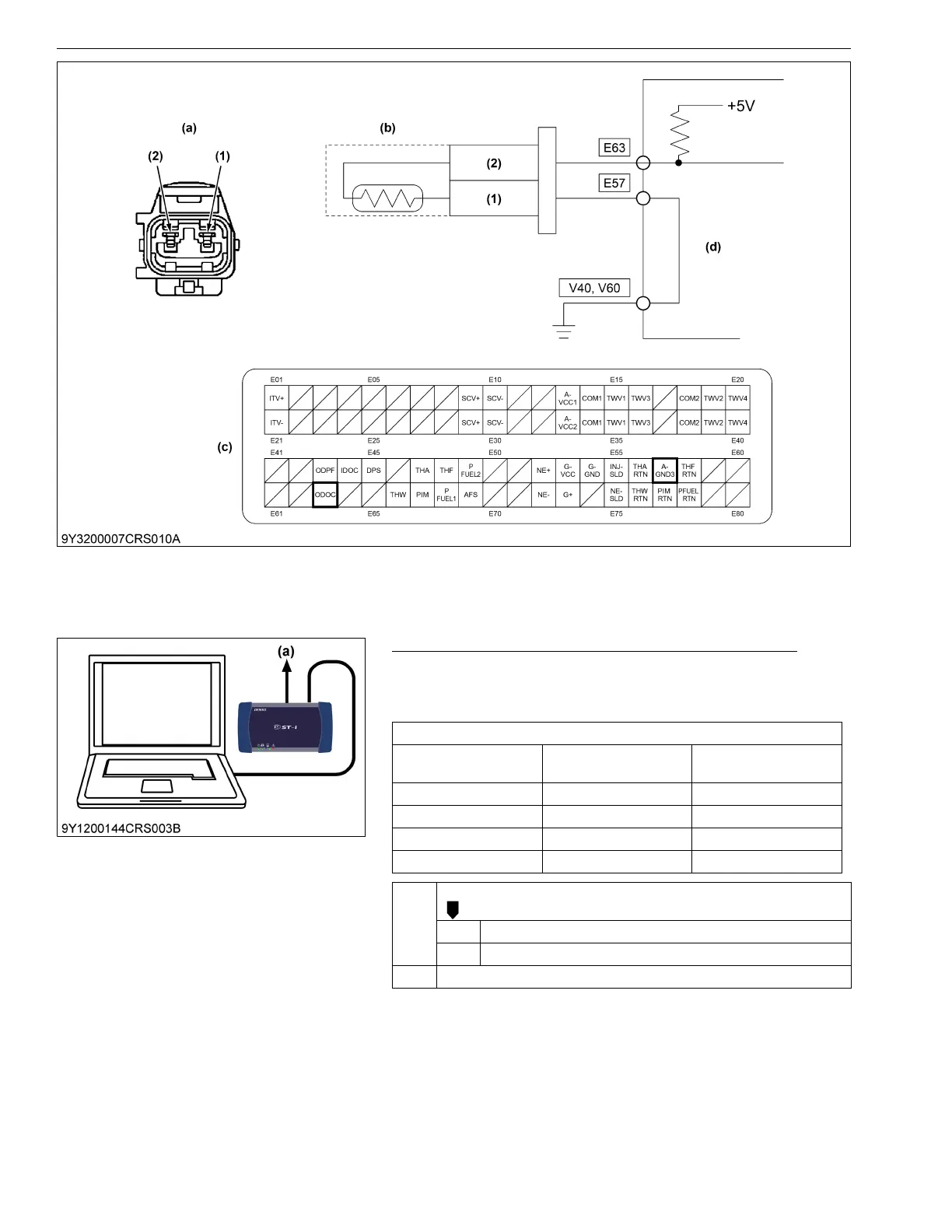
(1) Terminal A-GND3 (2) Terminal ODOC (a) Pin Assignment
(b) Exhaust Gas Temperature
Sensor (T
1
)
(c) Engine ECU Connector 1
(Engine Side)
(d) Engine ECU
Service specification
Actual exhaust gas
temperature
Exhaust gas
temperature
Output voltage
100 °C (212 °F) 100 °C (212 °F) Approx. 4.4 V
150 °C (302 °F) 150 °C (302 °F) Approx. 3.7 V
200 °C (392 °F) 200 °C (392 °F) Approx. 3.0 V
250 °C (482 °F) 250 °C (482 °F) Approx. 2.3 V
OK Clear the DTC and check whether it is output again or not.
OK Normal.
NG Replace the engine ECU.
NG Go to "2. Measure the Resistance Between Terminals".
(a) CAN1 Connector