COMMON RAIL SYSTEM
07-CR-E5,07-CR-TE5,07-CR-TIE5, DM
1-S228
9Y3200007CRS0346US0
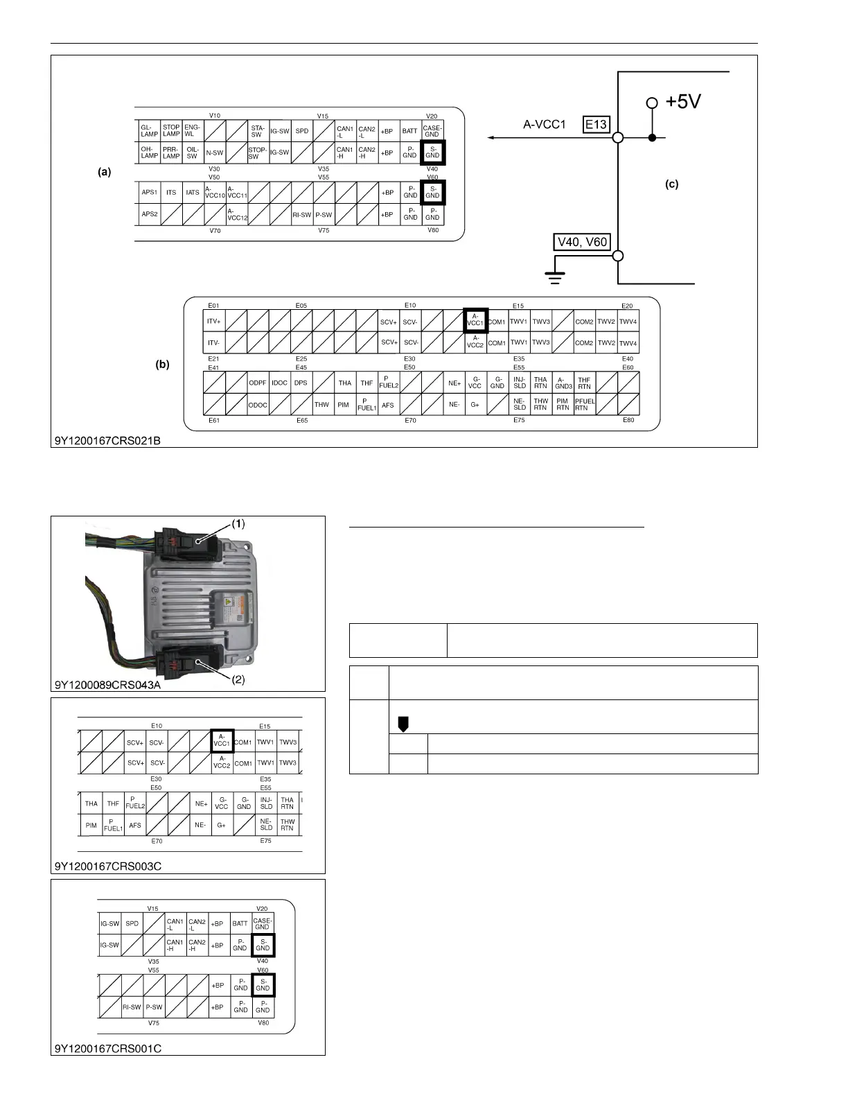
1. Measure the Engine ECU Terminal Voltage
1. Place the key switch in the OFF position, and unplug the engine
ECU wiring harness connector 1 (1) from the socket.
2. Move the key switch from the OFF to the ON position, and
measure the voltage between engine ECU terminals E13 and
V40 / V60.
9Y3200007CRS0347US0
(a) Engine ECU Connector 2
(Machine Side)
(b) Engine ECU Connector 1
(Engine Side)
(c) Engine ECU
Service
specification
Approx. 5 V
OK Check the wiring harness (Engine ECU terminal E13) for a short. →
Replace the faulty area.
NG Check the harness connectors and engine ECU pins.
OK Faulty engine ECU → Replace.
NG Replace the wiring harness, or replace the engine ECU.
(1) Engine ECU Wiring Harness
Connector 1 (Engine Side)
(2) Engine ECU Wiring Harness
Connector 2 (Machine Side)