COMMON RAIL SYSTEM
07-CR-E5,07-CR-TE5,07-CR-TIE5, DM
1-S247
1. Check the Intake Throttle Signal
1. After operating the engine, perform an active test.
Monitor the "Actual intake throttle valve opening" and "Intake
throttle opening output voltage", and check the values.
* For details, refer to the active test section.
2. Clear the DTC and check whether it is output again or not.
9Y3200007CRS0376US0
2. Checking Wiring Harness
1. Disconnect the sensors and the ECU from the connector.
2. Check the continuity of the harness.
• When checking the continuity of terminals, refer to the
sensor terminal and ECU terminal layouts on the detailed
pages of the corresponding DTCs.
NEW9Y3200007CRS0376-1US0
Service
specification
No DTC is output.
OK Normal.
NG Go to "2. Checking Wiring Harness".
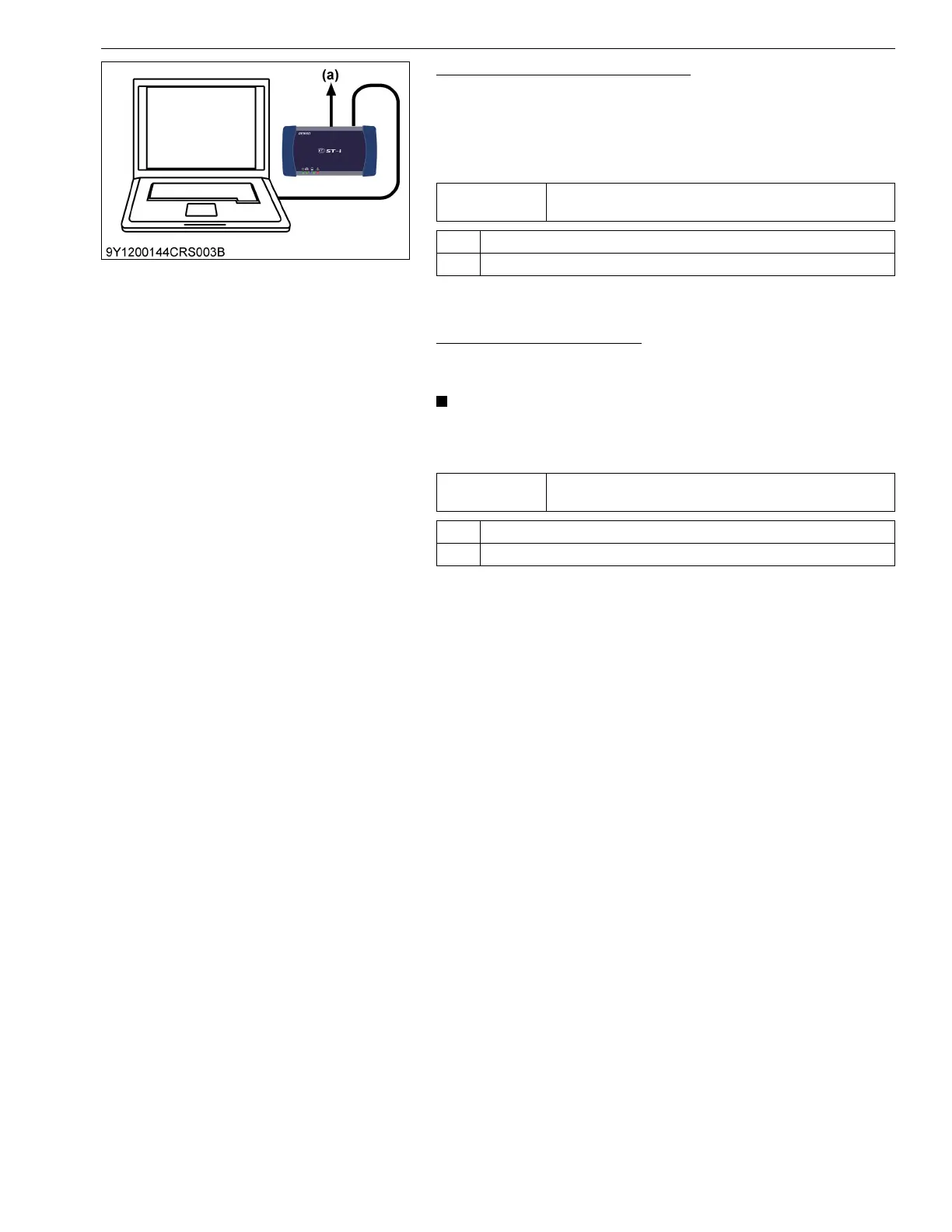
(a) CAN1 Connector
Service
specification
Conducting
OK Replace the intake throttle assembly.
NG Replace the wiring harness (connectors).