COMMON RAIL SYSTEM
07-CR-E5,07-CR-TE5,07-CR-TIE5, DM
1-S249
9Y3200007CRS0379US0
1. Check the Accelerator Position Sensor Signals
1. Place the key switch in the ON position, and check the
"Accelerator position" and "Accelerator position sensor 1 output
voltage" on the diagnosis tool data monitor.
• "Full close" and "Full open" are with the accelerator
position sensor, not with the accelerator pedal or hand
accelerator.
9Y3200007CRS0380US0
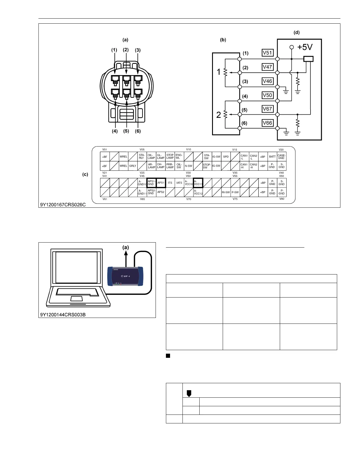
(1) Terminal A-VCC11
(2) Terminal APS1
(3) Terminal APS1 GND
(4) Terminal A-VCC10
(5) Terminal APS2
(6) Terminal APS2 GND
(a) Pin Assignment
(b) Accelerator Position Sensor
(c) Engine ECU Connector 2
(Machine Side)
(d) Engine ECU
Service specification
Actual accelerator pedal
position
Accelerator pedal
position
Output voltage
Fully close 0 %
1.35 V or lower
Follow the OEM
adjusted value:
1.1 to 1.35 V
Fully open 100 %
4.0 V or higher
Follow the OEM
adjusted value:
4.0 to 4.2 V
OK Clear the DTC and check whether it is detected again or not.
OK Normal.
NG Replace the engine ECU.
NG Go to "2. Measure the Voltage Between Sensor Terminals".
(a) CAN1 Connector