COMMON RAIL SYSTEM
07-CR-E5,07-CR-TE5,07-CR-TIE5, DM
1-S255
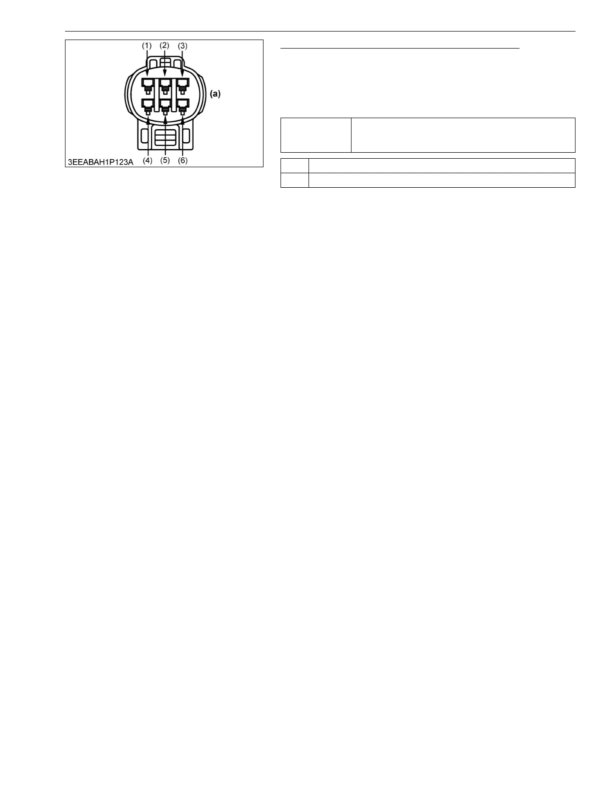
5. Measure the Voltage Between Sensor Terminals
1. Keep the accelerator position sensor connector plugged into
socket.
2. Measure the voltage between terminals (5) and (6) of
accelerator position sensor connector (at the machine wiring
harness side).
9Y3200007CRS0392US0
Service
specification
Accelerator pedal fully closed: 1.35 V or lower
Accelerator pedal full throttle: 4.0 V or higher
Follow the OEM adjusted value : 1.1 to 1.35 V, 4.0 to 4.2 V
OK Wiring harness open circuit, short → Check and replace.
NG Faulty accelerator sensor → Replace.
(1) Terminal A-VCC11
(2) Terminal APS1
(3) Terminal APS1 GND
(4) Terminal A-VCC10
(5) Terminal APS2
(6) Terminal APS2 GND
(a) Engine ECU