COMMON RAIL SYSTEM
07-CR-E5,07-CR-TE5,07-CR-TIE5, DM
1-S290
2. Check the DTC
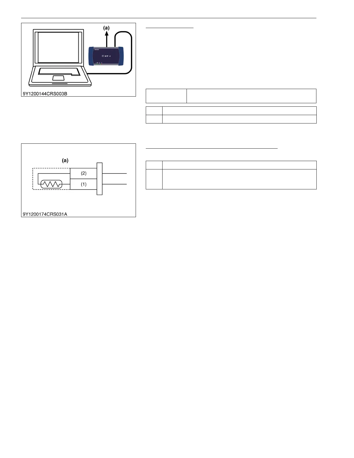
1. Place the key switch in the OFF position, and attach the
diagnosis tool to the CAN1 connector.
2. Turn the key switch to the ON position and select the "Exhaust
Gas Temperature sensor 0", "Exhaust gas temperature sensor
1" and "Exhaust gas temperature sensor 2" on the data
monitor.function.
3. Check whether the DTC is output or not after starting up the
engine by monitoring the data signals.
9Y3200007CRS0447US0
3. Check the Exhaust Gas Temperature Sensors
1. Check the exhaust gas temperature sensors (T
0
, T
1
and T
2
).
9Y3200007CRS0448US0
Service
specification
No DTC is output.
OK Normal.
NG Go to "3. Check the Exhaust Gas Temperature Sensor".
(a) CAN1 Connector
OK Normal.
NG Replace the exhaust gas temperature sensor or engine combustion main
parts. (Follow the diagnostic procedure of items P0543, P0546 and
P242C)
(1) Terminal A-GND3
(2) Terminal IDOC, ODOC or ODPF
(a) Exhaust Gas Temperature
Sesnsor (T
0
, T
1
and T
2
)