COMMON RAIL SYSTEM
07-CR-E5,07-CR-TE5,07-CR-TIE5, DM
1-S315
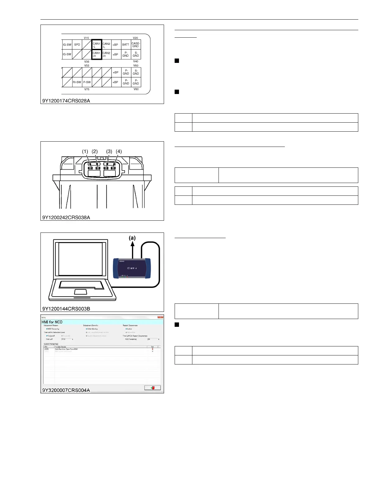
1. Check the Wiring Related to the CAN of the Common Rail
System
1. Check the connector and the wiring harness being connected to
engine ECU terminal V16 and V36 for a short or an open circuit.
• Refer to "6.[3] ELECTRIC SYSTEM INSPECTION
PROCEDURE - (1) Basics of Checking Electrical /
Electronic Circuit Systems". (Refer to page 1-S326)
• If the "CAN 1 Bus off error" is output at the same time, carry
out this inspection first.
9Y3200007CRS0498US0
2. Measure the EGR Terminal Voltage
1. Place the key switch in the ON position, and measure the
voltage between EGR terminals (3) and (4).
9Y3200007CRS0499US0
3. DTC Judgment
1. Place the key switch in the OFF position, attach the diagnosis
tool to the CAN1 connector, and return the key switch to the ON
position again.
2. Clear the DTC, and check whether the same DTC (U0076) is
output again or not.
3. Check the "HMI for NCD" screen and confirm that no warning is
displayed.
4. Check whether the device is under tampering.
• Check the DTC again after starting up the engine with the
engine with the coolant temperature over 50 °C (122 °F).
9Y3200007CRS0500US0
OK Go to "2. Measure the EGR Terminal Voltage".
NG Replace the faulty areas.
Service
specification
Approx. 10 to 16 V
OK Go to "3. DTC Judgment".
NG Replace the faulty areas.
(1) Terminal CAN-H
(2) Terminal CAN-L
(3) Terminal Ground
(4) Terminal Power (+12 V)
Service
specification
Normal (No DTC is output.)
OK Normal.
NG Replace the EGR assembly or engine ECU then "DTC Judgment" again.
(a) CAN1 Connector