COMMON RAIL SYSTEM
07-CR-E5,07-CR-TE5,07-CR-TIE5, DM
1-S41
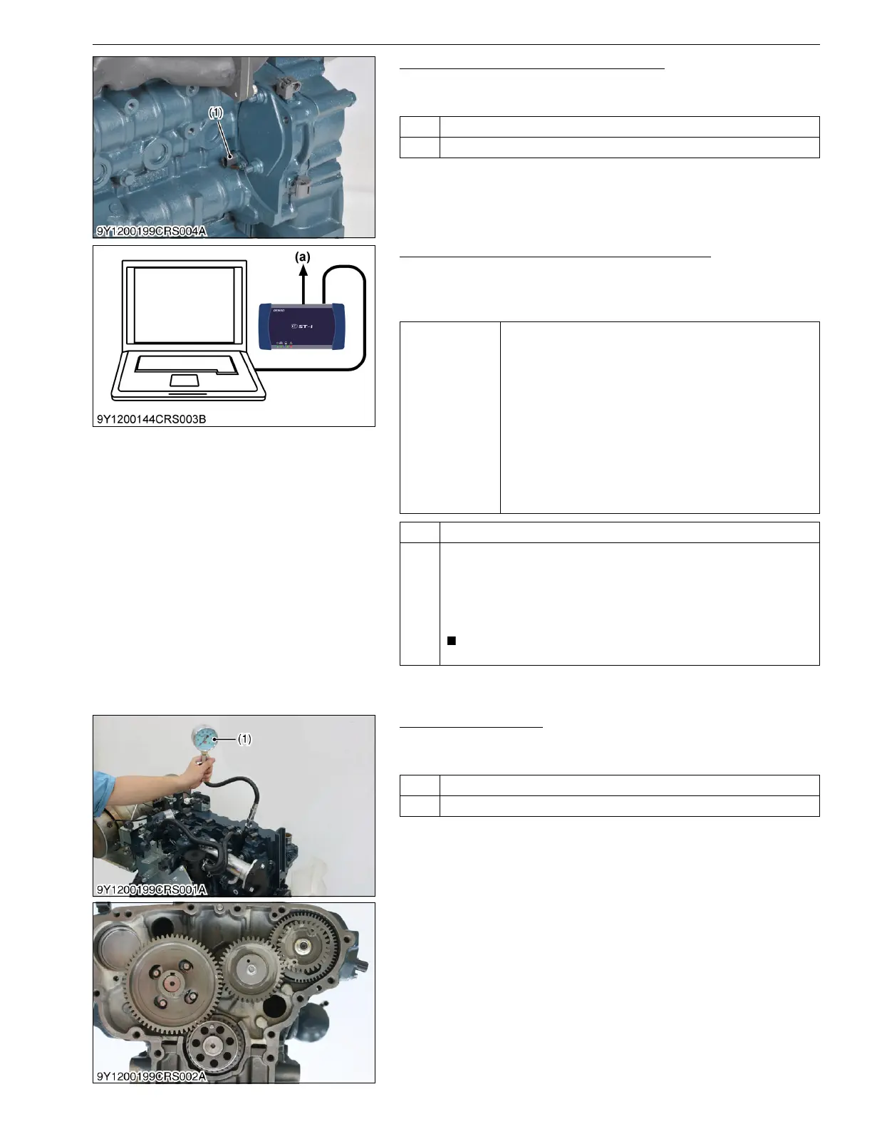
8. Check the Camshaft Position Sensor
1. Refer to DTC P0340 and P0341, and implement checking of the
camshaft position sensor.
9Y3200007CRS0050US0
9. Check the Data Related to Pressure Control
1. Measure the "Target rail pressure" and "Actual rail pressure"
when accelerator is operated as indicated below using the
diagnosis tool data monitor function.
9Y3200007CRS0051US0
10. Check the Engine
1. Check the compression pressure, valve timing and the inside of
the engine.
9Y3200007CRS0043US0
OK Go to "9. Check the Rail Pressure Sensor and Supply Pump".
NG Replace the camshaft position sensor-related parts.
(1) Camshaft Position Sensor
(G Sensor)
Service
specification
The "Actual rail pressure" always follow to the "Target rail
pressure".
1. When idling:
40 to 50 MPa (410 to 500 kgf/cm
2
, 5800 to 7200 psi)
2. Accelerator opening
0 → 100 % (During acceleration):
Maximum value 95.0 to 130 MPa (969 to 1320 kgf/cm
2
,
13800 to 18800 psi)
3. No-load maximum speed:
95.0 to 115 MPa (969 to 1170 kgf/cm
2
, 13800 to
16600 psi)
4. The numerical value is stable under normal operating and
the target value corresponds with actual pressure value.
OK Go to "10. Check the Engine"
NG (Check the trouble related to pressure
Refer to the pressure system items (P0087, P0088, P0089 and P0093
(Refer to page 1-S140)) and SCV abnormality items (P0628 and P0629
(Refer to 1-S223)) in "5.[2] DIAGNOSTIC PROCEDURE BY DTC",
perform diagnosis for the engine ECU, wiring harness and sensor, and
replace the required parts.
• Some diagnosis items above may be mentioned twice.
(a) CAN1 Connector
OK Normal.
NG Repair the malfunction.
(1) Compression Tester