COMMON RAIL SYSTEM
07-CR-E5,07-CR-TE5,07-CR-TIE5, DM
1-S51
6. Malfunction Verification - 2
1. Check for a large driving resistance due to problems in the
machine itself that do not involve the engine.
• Large resistance for actuation
• Tire air pressure
• Power transmission fault
• Brake drag
9Y3200007CRS0075US0
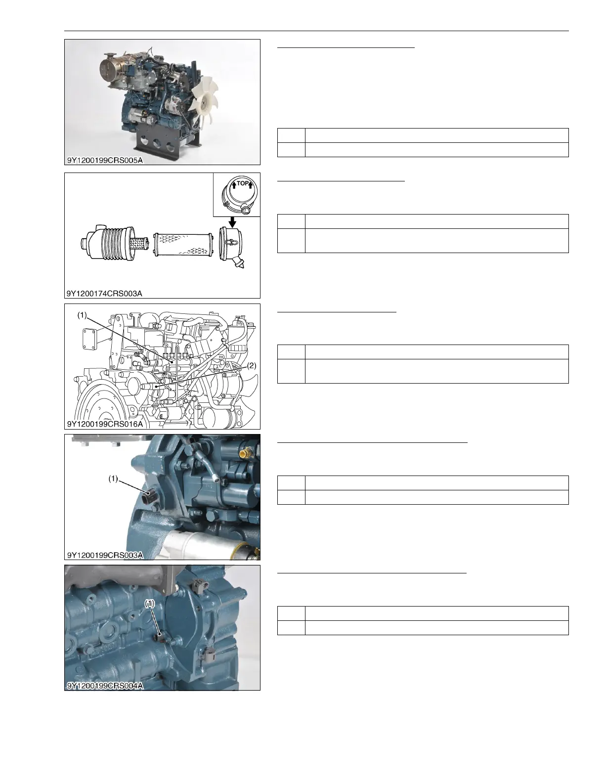
7. Check the Intake System
1. Check in accordance with "6.[1] AIR INTAKE SYSTEM
INSPECTION PROCEDURE". (Refer to page 1-S320)
9Y3200007CRS0076US0
8. Check the Fuel System
1. Check in accordance with "6.[2] FUEL SYSTEM INSPECTION
PROCEDURE". (Refer to page 1-S321)
9Y3200007CRS0077US0
9. Check the Crankshaft Position Sensor
1. Refer to DTC P0335 and P0336, and implement checking of the
crankshaft position sensor.
9Y3200007CRS0078US0
10. Check the Camshaft Position Sensor
1. Refer to DTC P0340 and P0341, and implement checking of the
camshaft position sensor.
9Y3200007CRS0079US0
OK Go to "7. Check the Intake System".
NG Repair or adjust the malfunction.
OK Go to "8. Check the Fuel System".
NG Repair in accordance with "6.[1] AIR INTAKE SYSTEM INSPECTION
PROCEDURE". (Refer to page 1-S320)
OK Go to "9. Check the Crankshaft Position Sensor".
NG Repair in accordance with "6.[2] FUEL SYSTEM INSPECTION
PROCEDURE". (Refer to page 1-S321)
(1) Rail (2) Supply Pump
OK Go to "10. Check the Camshaft Position Sensor".
NG Replace the crankshaft position sensor-related parts.
(1) Crankshaft Position Sensor
(NE Sensor)
OK Go to "11. Check the Rail Pressure Sensor and Supply Pump".
NG Replace the camshaft position sensor-related parts.
(1) Camshaft Position Sensor
(G Sensor)