59 / 123Issued: 13.08.2012 Version: KST PLC mxAutomation Logix 1.0 V1 en (PDF)
7 Programming
Memory
Inputs
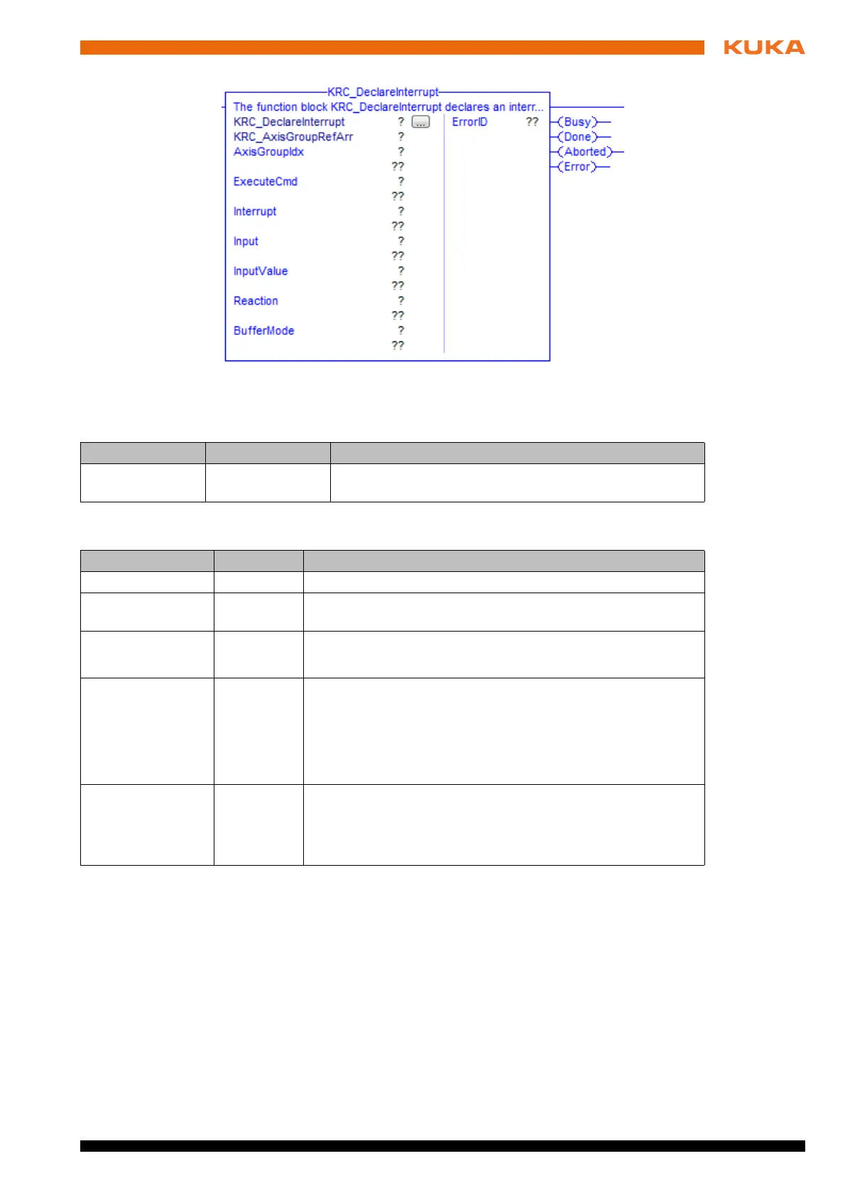
Fig. 7-30: Function block KRC_DeclareInterrupt
Parameter Type Description
KRC_AxisGroup
RefArr
AXIS_GROUP_
REF_ARR
Reference to the internal structure of the axis group
Parameter Type Description
AxisGroupIdx INT Index of axis group
ExecuteCmd BOOL The statement is buffered in the case of a rising edge of the
signal.
Interrupt INT Number of the interrupt
1 … 8
Input INT Number of the digital input to which the interrupt is declared
1 … 2,048
Note: It must be ensured that no inputs are used that are
already assigned by the system. Example: $IN[1025] is
always TRUE.
InputValue BOOL TRUE = statement is executed in the case of a rising edge of
the signal.
FALSE = statement is executed in the case of a falling edge
of the signal.
 Loading...