17 / 123Issued: 13.08.2012 Version: KST PLC mxAutomation Logix 1.0 V1 en (PDF)
6 Start-up and configuration
6 Start-up and configuration
6.1 Start-up and configuration – overview
6.2 Configuring message generation on an external system
Messages generated on the smartHMI can be transferred to up to 5 external
systems, e.g. a cell visualization system, via the UDP/IP protocol. The mes-
sage text and the associated message elements are sent in the language that
is set on the smartHMI.
Procedure 1. In the main menu, select Configuration > mxAutomation > Messages.
The configuration window is opened.
2. Enter a name for the channel.
3. Enter the IP address and port number of the external system.
4. Configure the filter for the message type.
5. Press Save. The configuration is saved. At the same time, a ping is sent
to the external system to check whether the external system is accessible.
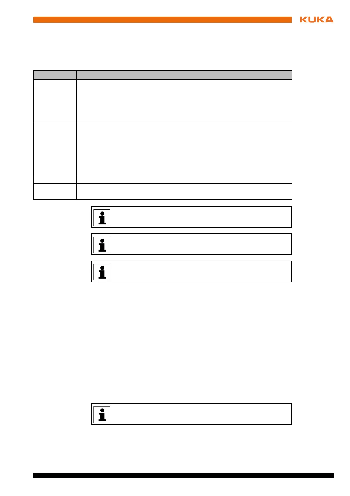
Step Description
1 Transfer a project from the robot controller to WorkVisual.
2 Configure EtherNet/IP in WorkVisual.
Note: The MxA_Rockwell_Sample.wvs template supplied on the USB stick
(Template folder) contains a sample WorkVisual project with the correct Ether-
Net/IP settings.
3 Map the I/Os of the robot controller to the EtherNet/IP signals in WorkVisual:
Map inputs 2,049 to 4,016 to the EtherNet/IP inputs from address 0.0 on-
wards.
Map outputs 2,049 to 4,016 to the EtherNet/IP outputs from address 0.0 on-
wards.
Note: The I/O range 4,017 to 4,080 must remain unused.
4 Transfer the project from WorkVisual to the robot controller and activate it.
5 Compare the project in WorkVisual with the project on the robot controller and
accept the differences in the WorkVisual project.
Information about the configuration of EtherNet/IP on the robot con-
troller can be found in the KR C4 EtherNet/IP documentation.
Information about configuring EtherNet/IP on the higher-level control-
ler can be found in the documentation for the RSLogix 5000 software.
Information about bus configuration and project deployment can be
found in the WorkVisual documentation.
During operation, a heartbeat signal is transmitted via all configured
channels at an interval of 5 minutes.
 Loading...