64 / 123 Issued: 13.08.2012 Version: KST PLC mxAutomation Logix 1.0 V1 en (PDF)
KUKA.PLC mxAutomation Logix 1.0
Memory
Inputs
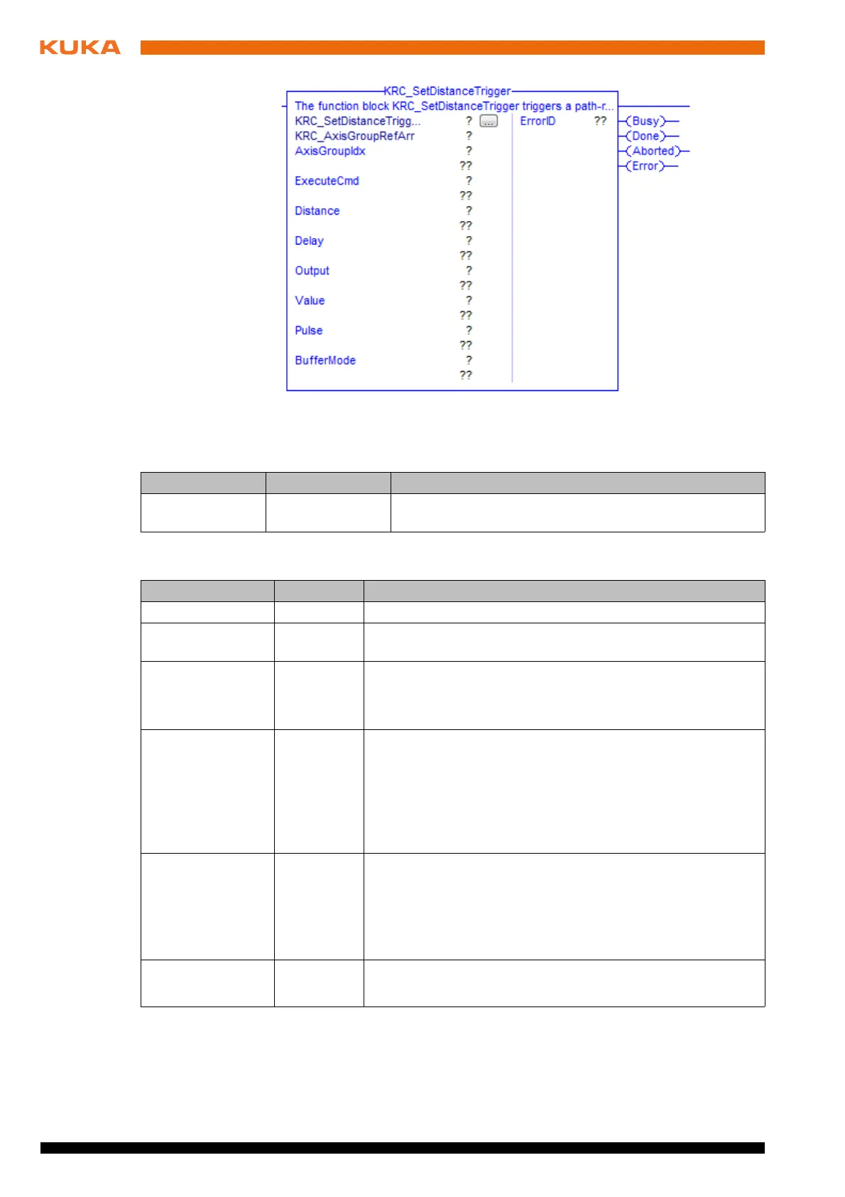
Fig. 7-34: Function block KRC_SetDistanceTrigger
Parameter Type Description
KRC_AxisGroup
RefArr
AXIS_GROUP_
REF_ARR
Reference to the internal structure of the axis group
Parameter Type Description
AxisGroupIdx INT Index of axis group
ExecuteCmd BOOL The statement is buffered in the case of a rising edge of the
signal.
Distance INT Switching point of the trigger
0: Switching action at the start point
1: Switching action at the end point
Delay INT Statement delay
Delay = 0 ms: no delay
The statement cannot be shifted freely in time. The shifts that
are available depend on the value selected for Distance. Fur-
ther information about this is contained in the Operating and
Programming Instructions for System Integrators.
Output INT Number of the digital output
1 … 2,048
Note: It must be ensured that no outputs are used that are
already assigned by the system. Example: $OUT[1025] is
always TRUE.
Value BOOL TRUE = activate output
FALSE = deactivate output
 Loading...