66 / 123 Issued: 13.08.2012 Version: KST PLC mxAutomation Logix 1.0 V1 en (PDF)
KUKA.PLC mxAutomation Logix 1.0
Memory
Inputs
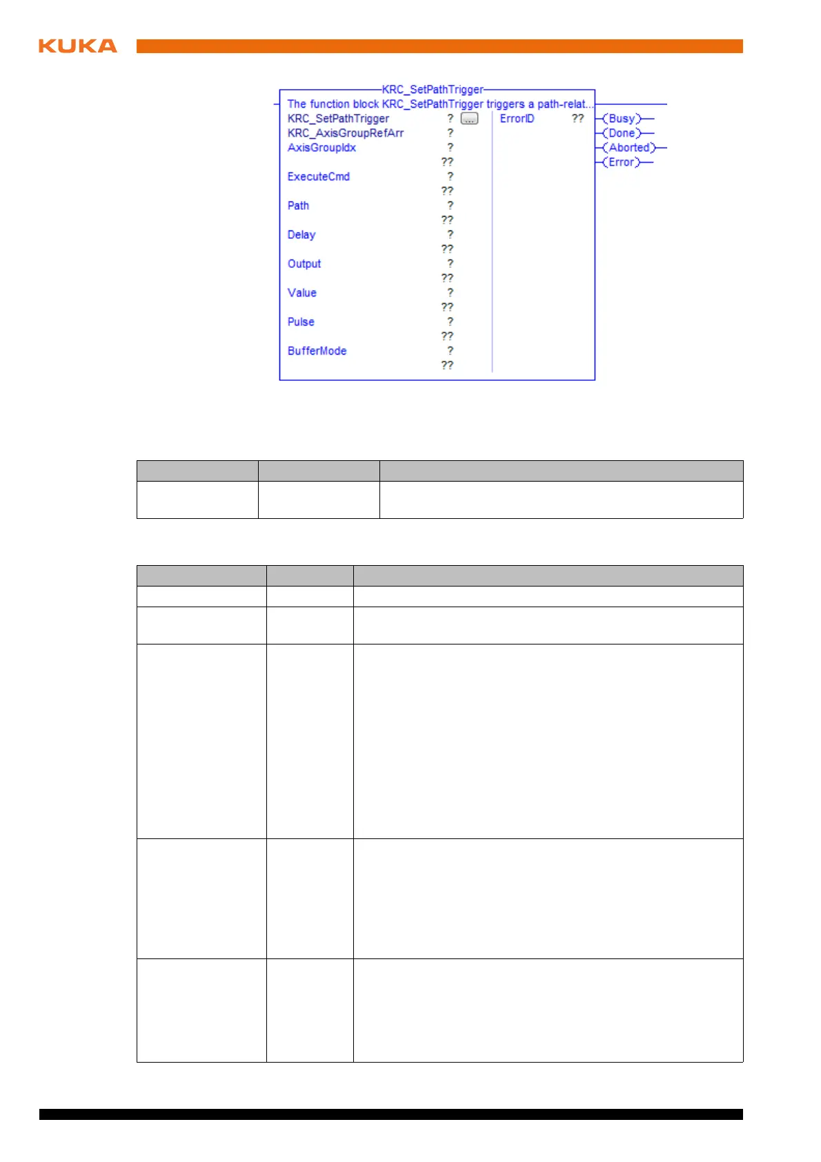
Fig. 7-35: Function block KRC_SetPathTrigger
Parameter Type Description
KRC_AxisGroup
RefArr
AXIS_GROUP_
REF_ARR
Reference to the internal structure of the axis group
Parameter Type Description
AxisGroupIdx INT Index of axis group
ExecuteCmd BOOL The statement is buffered in the case of a rising edge of the
signal.
Path REAL Statement offset
If the statement is to be shifted in space, the desired distance
from the end point must be specified here. If this end point is
approximated, Path is the distance to the position on the
approximate positioning arc closest to the end point.
Delay = 0.0 mm: no offset
Delay > 0.0 mm: shifts the statement towards the end of
the motion.
Delay < 0.0 mm: shifts the statement towards the start of
the motion.
Delay INT Statement delay
Delay = 0 ms: no delay
The statement cannot be shifted freely in time. The offsets
that are possible depend on the value selected for Path. Fur-
ther information about this is contained in the Operating and
Programming Instructions for System Integrators.
Output INT Number of the digital output
1 … 2,048
Note: It must be ensured that no outputs are used that are
already assigned by the system. Example: $OUT[1025] is
always TRUE.
 Loading...