89 / 123Issued: 13.08.2012 Version: KST PLC mxAutomation Logix 1.0 V1 en (PDF)
7 Programming
Memory
Inputs
Outputs
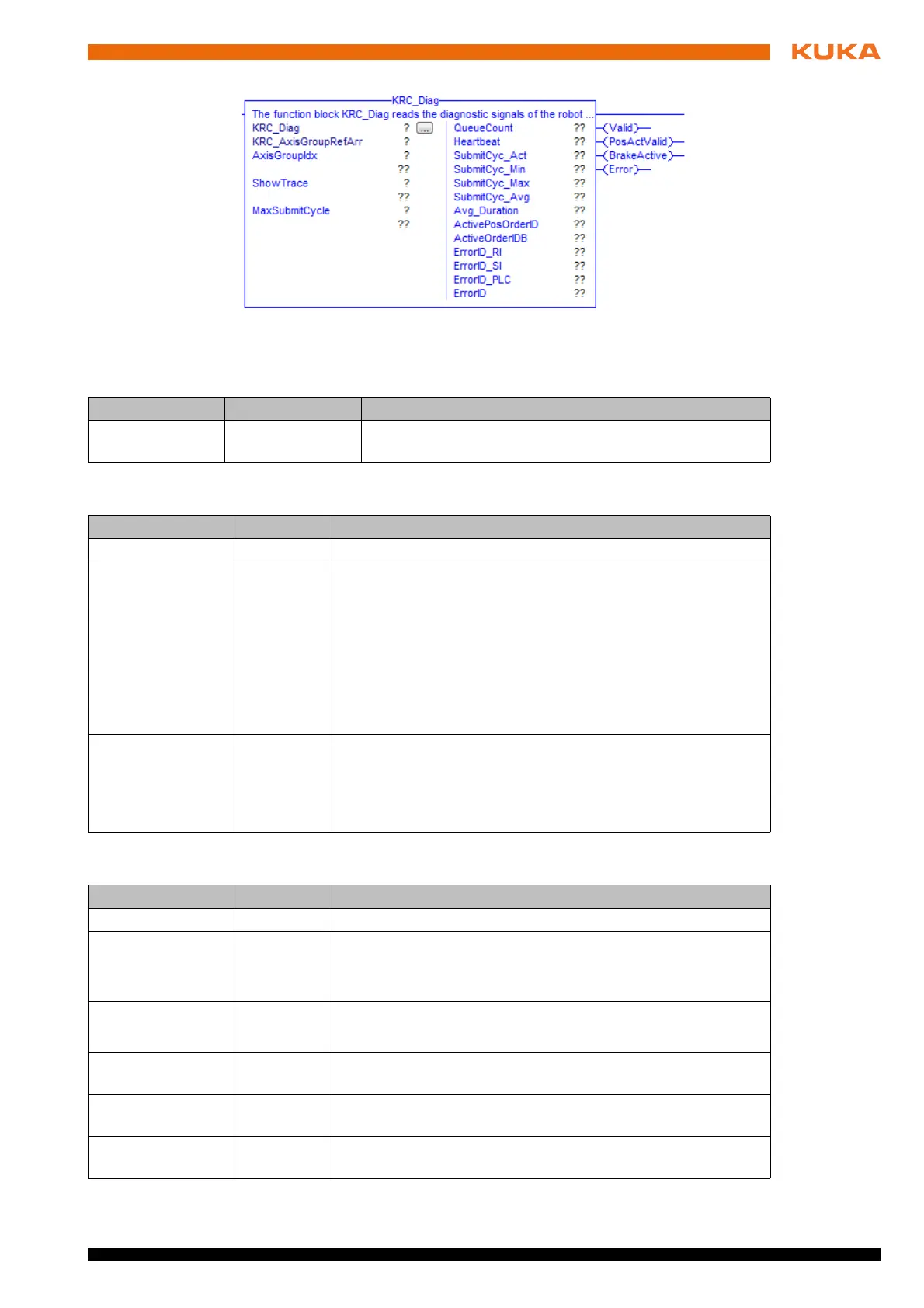
Fig. 7-52: Function block KRC_Diag
Parameter Type Description
KRC_AxisGroup
RefArr
AXIS_GROUP_
REF_ARR
Reference to the internal structure of the axis group
Parameter Type Description
AxisGroupIdx INT Index of axis group
ShowTrace BOOL TRUE = activate display of the active function blocks in the
message window of the KUKA smartHMI.
FALSE = deactivate display of the active function blocks in
the message window of the KUKA smartHMI.
Note: Only activate the display for test and diagnostic pur-
poses. If the display is active, approximate positioning is no
longer possible and the cycle time of the Submit interpreter is
adversely affected.
MaxSubmitCycle INT Maximum cycle time of the Submit interpreter
Default: 1,000 ms
Note: If the maximum cycle time is exceeded, the
$MOVE_ENABLE signal for motion enable is reset.
Parameter Type Description
QueueCount INT Number of buffered statements
Heartbeat INT Heartbeat signal of the Submit interpreter (counter is incre-
mented by every Submit cycle)
1 … 245
SubmitCyc_Act REAL Current cycle time of the Submit interpreter; unit: ms
Mean value over 1,000 ms = 1/number of cycles per second
SubmitCyc_Min REAL Shortest cycle time of the Submit interpreter since the last
broken connection; unit: ms
SubmitCyc_Max REAL Longest cycle time of the Submit interpreter since the last
broken connection; unit: ms
SubmitCyc_Avg INT Mean value of the cycle time of the Submit interpreter during
the calculation period Avg_Duration; unit: ms
 Loading...