PC2R Disassembly/Assembly
Opening the PC2R
3-3
Removing the Connector Board
1. Following Steps 2– 5, disconnect the cables listed in Table 3-1.
2. Disconnect the stranded wire cable from J301 on the Connector Board.
3. Remove the cable locking clip and disconnect the flat ribbon cable from J304. Be sure to set
the cable locking clip safely aside so that you can install it when you reconnect the cable.
4. Disconnect the stranded wire cable from J322.
5. The flat ribbon cables connected to J302 and J303 use wire trap connectors. The shielding
has been removed from these cables to expose the wires. The wires are directly inserted
into these connectors.
Lift up the sides of each connector. This unlocks the trap to free the cable wires. Gently
pull each cable up out of the connector. Note the marking (red or black) on each cable that
indicates the connection to Pin 1; you’ll need to reconnect the marked edge of the cable to
Pin 1 when you replace the Connector Board.
6. Remove the two screws that secure the MIDI jacks to the rear panel.
7. Remove the two nuts that secure the 1/4” audio out jacks to the rear panel.
8. Remove the three screws that secure the Connector Board to the bottom enclosure.
Caution: VR1 on the Connector Board is attached to the heat sink. When you remove the
Connector Board and heat sink, be sure to keep the board and heat sink stable so that you
do not damage VR1 or its connection.
9. Remove the four screws that secure the heat sink to the bottom enclosure.
10. Slide the Connector Board and heat sink away from the rear panel and toward the Front
Panel Assembly. This will free the jacks and MIDI switch from their positions on the rear
panel.
11.Tilt up the rear panel edge of the Connector Board and heat sink. Carefully lift the board
and heat sink out of the PC2R, and place them on a flat protected surface.
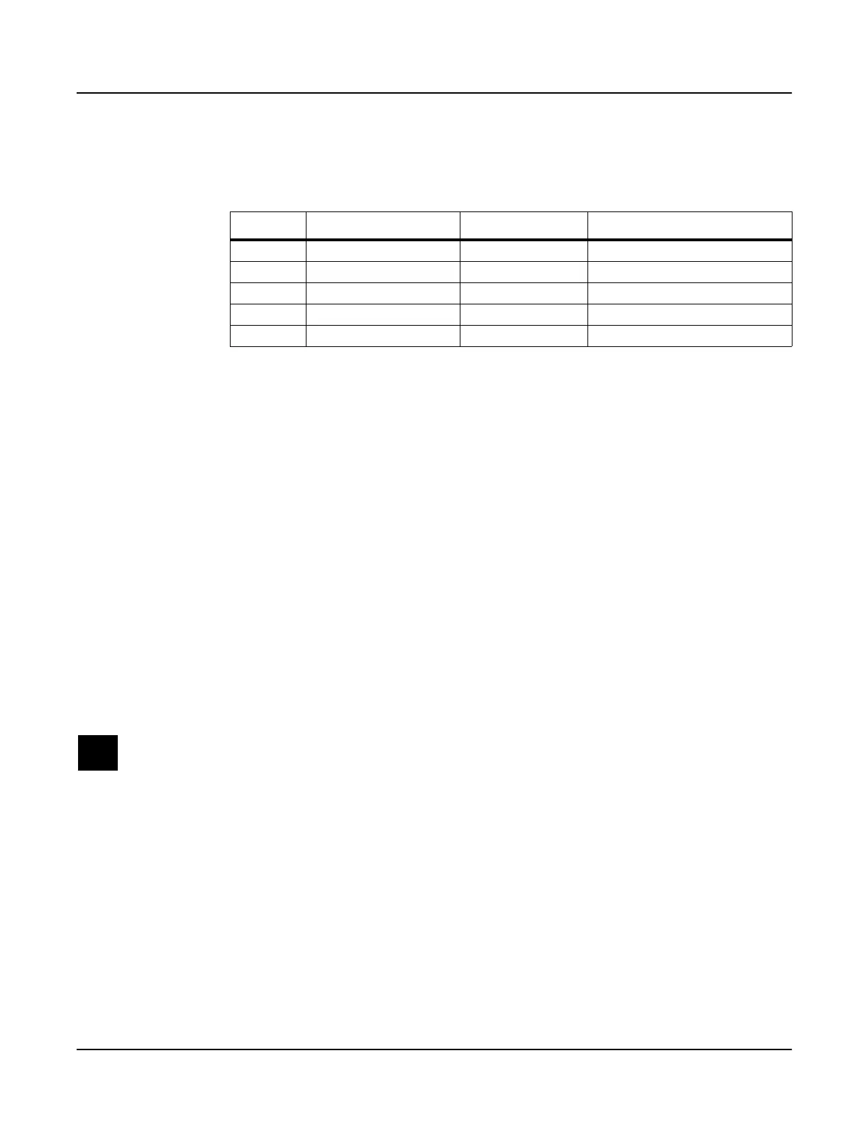
Ref. Name Cable Type Destination
J301 PC2 Power stranded wire Engine Board
J302 PC2R Audio In flat ribbon Engine Board
J303 MIDI/CPU flat ribbon Engine Board
J304 Front Panel flat ribbon Right Front Panel Board
J322 FP/Vol/Pwr/Hp stranded wire Headphone/Vol/Pwr Sw Board
Table 3-1 Connector Board cables

 Loading...