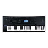
PC2/PC2X Disassembly/Assembly
Top Enclosure
4-15
Caution: Each switch button cap uses a set of small pegs to mount the cap to the Slider
Board. The button caps are mounted individually or in clusters. If a cap becomes
separated from the board, be careful that a peg is not inadvertently broken.
Replacing the Slider Board
1. Position the Slider Board onto the top enclosure. Raise the top enclosure up slightly to
verify that the slider knobs and switch button caps are correctly positioned through their
openings in the top enclosure.
2. Align the center screw hole on front panel edge with the thread marks in the extrusion
and install the screw that secures the front panel edge of the Slider Board. See Figure 4-9.
3. Place the PC board clamp in position. Align the center screw holes of the PC board clamp
with the thread marks in the extrusion and install the two screws that secure the PC board
clamp.
4. Connect the wire trap flat ribbon cables in the following order.
Caution: Be sure to look for the marking on the edge of the cable denoting Pin 1 and that
you match it correctly with Pin 1 on the board. Make certain that the wires are straight
prior to inserting them into the connector and that each wire is correctly inserted into its
respective position.
Note: Be sure the sides of the connector are lifted. Insert the flat ribbon cables into the
wire trap connectors and push down the sides of each connector to lock the cable into the
connector. Gently pull each cable to verify that it is locked into its connector.
Insert the seven-wire flat ribbon cable from the Connector Board into the wire trap
connector at J101 on the Slider Board.
Insert the eight-wire flat ribbon cable from the Front Panel Board into the wire trap
connector at J102 on the Slider Board.
5. If the unit you are servicing has a PCX-1 Board, follow the procedure on page 4-13 to
install it.
6. Follow the procedure on page 4-8 to install the left enclosure support wall.
Removing the Engine Board
1. Follow the procedure described on page 4-8 to remove the left enclosure support wall.
2. If the unit you are servicing has a PCX-1 Board installed, remove it following the
procedure described on page 4-13.
3. Following Steps 4–6, disconnect the cables listed in Table 4-4.
 Loading...


