PC2R Disassembly/Assembly
Opening the PC2R
3-5
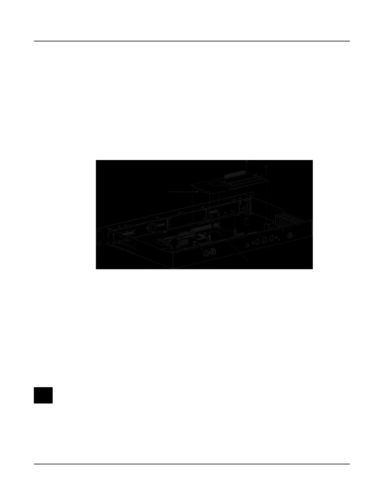
Removing the Polyphony Expansion Board (PCX-1)
The Polyphony Expansion Board is mounted onto the Engine Board and held in place with four
nylon PC board standoffs and a 24-pin female connector on the underside of the board. It is also
secured to the bottom enclosure with two screws.
1. Remove the two screws that secure the PCX-1 Board to the bottom enclosure.
2. Squeeze the top of one of the four nylon PC board standoffs, and lift the corner of the
board until it clears that standoff. Repeat for the other three standoffs.
3. When the board is free of the standoffs, lift the board straight up to disconnect the 24-pin
connector from the Engine Board.
Figure 3-3 Removing the Polyphony Expansion Board (PCX-1)
Replacing the Polyphony Expansion Board (PCX-1)
There are two cables routed underneath the PCX-1 Board: a flat ribbon cable from the LCD to
the Engine Board, and a stranded wire cable from the Headphone/Volume/Power Switch
Board to the Connector Board. Before you replace the PCX-1 Board, be certain that these cables
are properly positioned.
1. Place the PCX-1 Board over the four standoffs. This should properly position the 24-pin
connector over the 24-pin header on the Engine Board.
2. Press the PCX-1 Board down, securing the 24-pin connector, and snapping the board onto
the standoffs.
Note: If you are installing a new PCX-1 Board, check the old board for Sound ROM
options. If the unit has Sound ROM options, be sure to install them on the new board.
3. Install the two screws that secure the PCX-1 Board to the bottom enclosure.
24-pin male header
on Engine board
24-pin female connector
on PCX-1 board

 Loading...