3-6
PC2R Disassembly/Assembly
Opening the PC2R
Removing the Engine Board
1. If the PC2R you are servicing has a PCX-1 Board installed, remove it following the
procedure described on page 3-5.
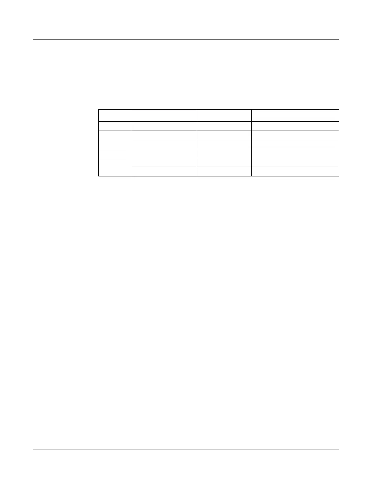
2. Following Steps 3–6, disconnect the cables listed in Table 3-2.
3. Remove the cable locking clip and disconnect the flat ribbon cable from J304 on the
Connector Board. Be sure to set the cable locking clip safely aside so that you can install it
when you reconnect the cable.
4. The flat ribbon cables connected to J403 and J412 use wire trap connectors. The shielding
has been removed from these cables to expose the wires. The wires are directly inserted
into these connectors.
Lift up the sides of each connector. This unlocks the trap to free the cable wires. Gently
pull each cable up out of the connector. Note the marking (red or black) on each cable that
indicates the connection to Pin 1; you’ll need to reconnect the marked edge of the cable to
Pin 1 when you replace the Engine Board.
5. Remove the cable locking clip and disconnect the flat ribbon cable from location J406 on
the Engine Board. Be sure to set the cable locking clip safely aside so that you can install it
when you reconnect the cable.
6. Disconnect the stranded wire cables from locations J402 and J405 on the Engine Board.
7. Remove the five screws that secure the Engine Board to the bottom enclosure and remove
the Engine Board.
Replacing the Engine Board
1. Place the Engine Board on the bottom enclosure.
2. Install the five screws that secure the Engine Board to the bottom enclosure.
3. Connect the stranded wire cable from the Connector Board to J402.
4. Connect the stranded wire cable from the LCD Board to J405.
5. Connect the flat ribbon cable from the LCD Board to J406. Be sure to install the cable
locking clip.
6. Connect the wire trap flat ribbon cables in the following order.
Ref. Name Cable Type Destination
J304 Front Panel flat ribbon RIght Front Panel to Connector
J402 PC2 Power stranded wire Connector Board
J403 MIDI/CPU flat ribbon Connector Board
J405 Backlight stranded wire LCD Board
J406 LCD flat ribbon LCD Board
J412 PC2 Audio Out flat ribbon Connector Board
Table 3-2 Engine Board cables

 Loading...