PC2R Disassembly/Assembly
Front Panel Assembly
3-13
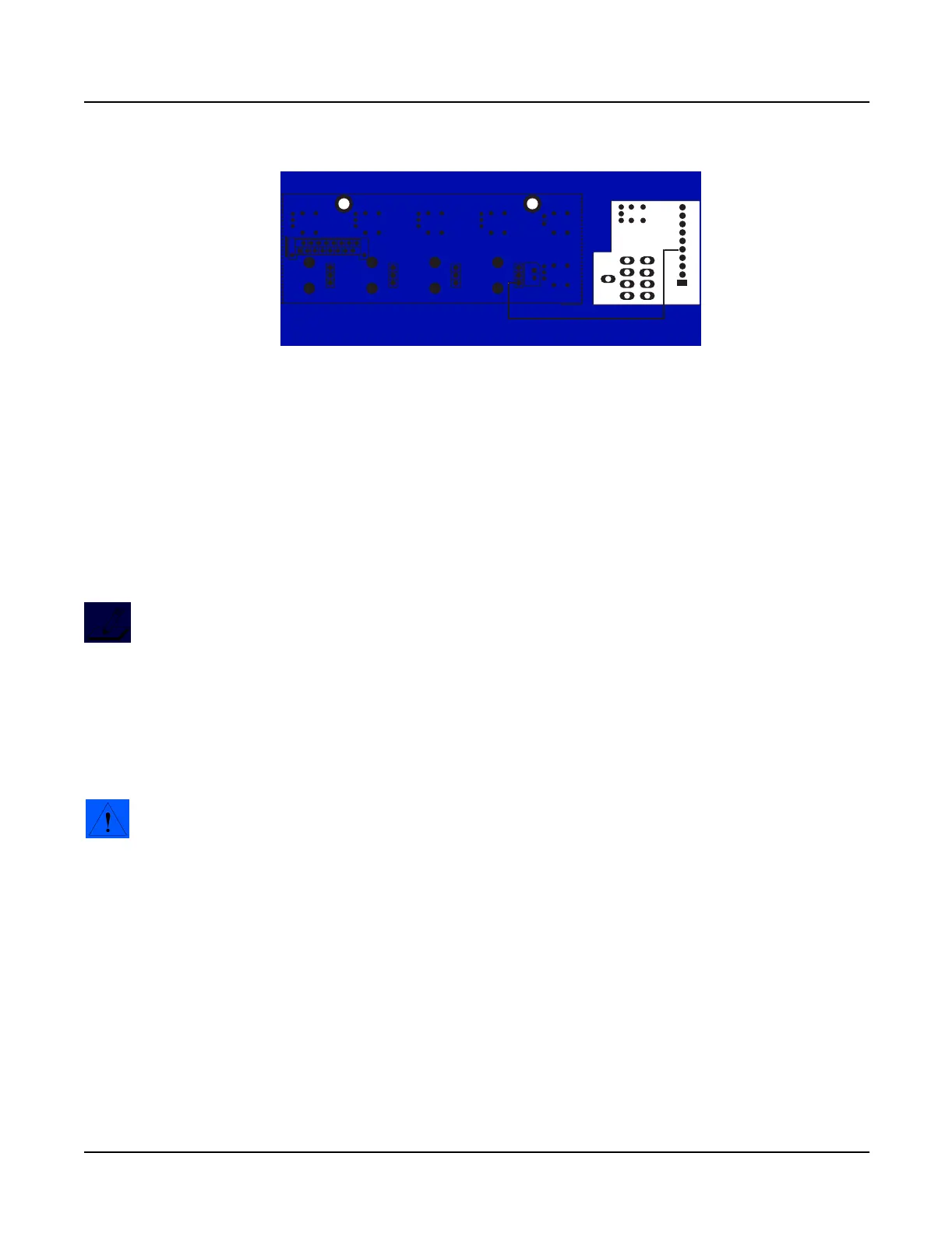
Figure 3-6 Left Front Panel and Headphone/Volume/Power Switch Board
connection
6. Remove the Left Front Panel Board.
Replacing the Left Front Panel Board
1. Place the Left Front Panel Board in position on the mounting bracket and line up the
screw holes.
2. Install the two screws that secure the board to the mounting bracket.
Note: Verify that the rotary potentiometers and switch button caps are correctly
positioned through their openings in the front panel faceplate. Turn the rotary
potentiometers to be sure that they move freely; and push the switch button caps to be
sure that their corresponding switches click.
3. Install the screw that secures the front panel faceplate.
4. Connect the flat ribbon cable from the Right Front Panel Board to the Left Front Panel
Board, location J603.
Caution: The side walls of the picoflex header are different. The Pin 1 side is slightly
wider than the other side; and the corresponding sides of the connector incorporate the
differences. When you connect the cable, be sure to orient the marking (red or black) on
the cable that indicates the connection to Pin 1 on the board to prevent damage to the
header, connector or a failure caused by an improper connection.
5. Refer to Figure 3-6. Solder the wire connection from the Headphone/Volume/Power
Switch Board to the location indicated on the Left Front Panel Board.
6. Follow the procedure on page 3-8 to install the Front Panel Assembly.
J604
J603
Circuit side
1
Left Front Panel Board
HP/Vol/Pwr Sw
Board
1
J2
J1
soldered
connection

 Loading...