3-8
PC2R Disassembly/Assembly
Front Panel Assembly
Front Panel Assembly
The Front Panel Assembly consists of the front panel faceplate, a mounting bracket for the front
panel boards, and four printed circuit boards. The boards mounted on the Front Panel Assembly
are the Right Front Panel, LCD, Left Front Panel, and Headphone/Volume/Power Switch.
Removing the Front Panel Assembly
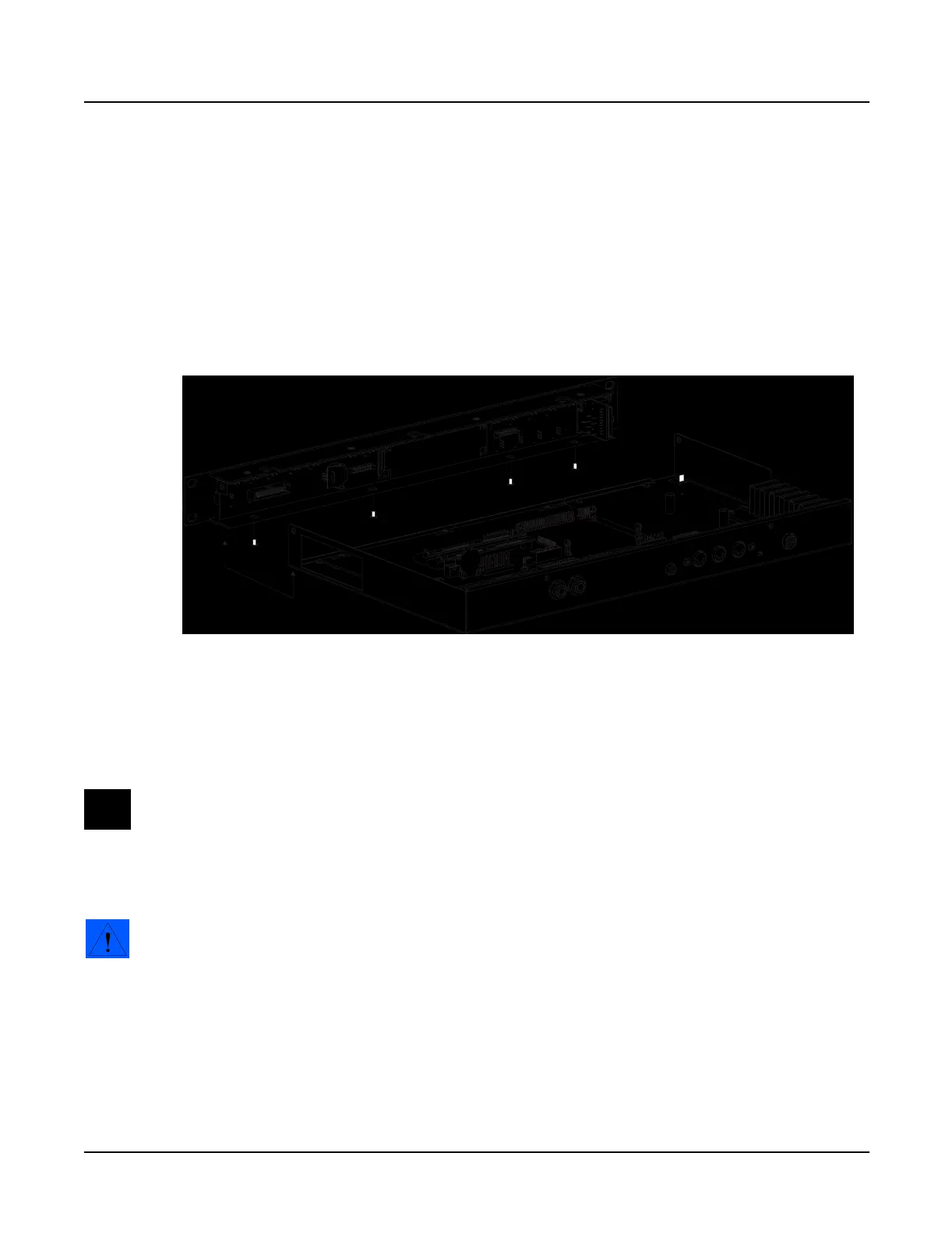
Refer to Figure 3-4. The bottom edge of the Front Panel Assembly and front edge of the bottom
enclosure connect to form a lip.
Figure 3-4 Front Panel Assembly and bottom enclosure
1. Tilt up the front edge of the PC2R.
2. Using a #1 screwdriver, remove the four screws that secure the Front Panel Assembly to
the bottom enclosure.
Note: Before continuing, be sure that you have a soft surface to rest the Front Panel
Assembly on so that the front panel switches, jacks, and rotary potentiometers are not
damaged.
3. Slide the Front Panel Assembly forward and away from the bottom enclosure.
Caution: There are four cables connected to the Front Panel Assembly. You do not need to
disconnect these cables.
Replacing the Front Panel Assembly
1. Position the Front Panel Assembly so that its bottom edge is under the front edge of the
bottom enclosure.
2. Tilt up the front edge of the PC2R and install the four black flat head machine screws.
Lip

 Loading...