4-8
PC2/PC2X Disassembly/Assembly
Top Enclosure
Removing the Enclosure Support Walls
Left Enclosure Support Wall
1. Remove the four screws that secure the left enclosure support wall to the top enclosure,
and remove the left enclosure support wall.
Right Enclosure Support Wall
1. Remove the six screws that secure the right enclosure support wall to the top enclosure,
and remove the right enclosure support wall.
Replacing the Enclosure Support Walls
Left Enclosure Support Wall
1. Align the center screw holes of the three-hole groupings in the left enclosure support wall
with the thread marks in the extrusion.
2. Install the four screws that secure the left enclosure support wall to the top enclosure.
Right Enclosure Support Wall
1. Align the center screw holes of the three-hole groupings in the right enclosure support
wall with the thread marks in the extrusion.
2. Install the six screws that secure the right enclosure support wall to the top enclosure.
Removing the Connector Board
1. Follow the procedure described on page 4-8 to remove the right enclosure support wall.
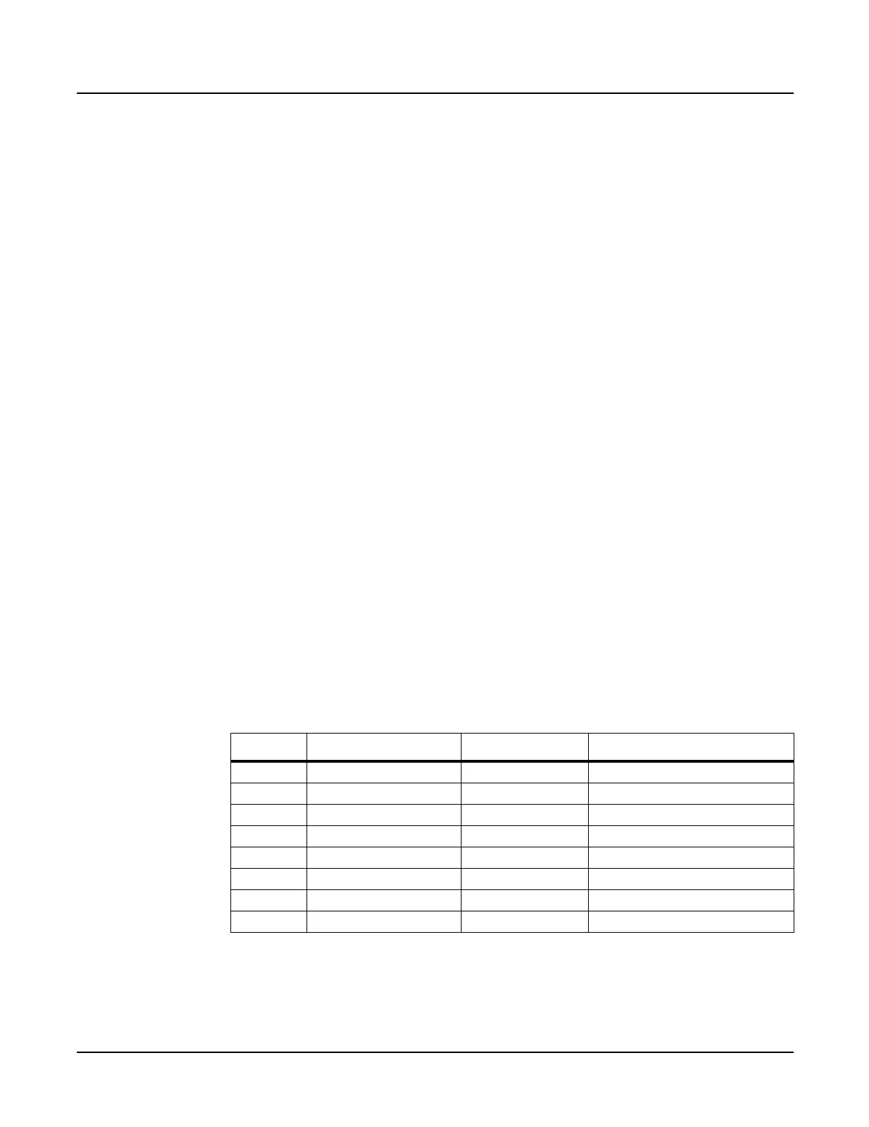
2. Following Steps 3–5, disconnect the cables listed in Table 4-2.
3. Disconnect the stranded wire cable from J301 on the Connector Board.
Ref. Name Cable Type Destination
J301 PC2 Power stranded wire Engine Board
J302 Audio flat ribbon Engine Board
J303 MIDI/CPU flat ribbon Engine Board
J304 Front Panel flat ribbon Front Panel Board
J305 Slider flat ribbon Slider Board
J306 Treble flat ribbon Keyboard Assembly
J307 Bass flat ribbon Keyboard Assembly
J308 Wheels flat ribbon Mod Wheel Assembly
Table 4-2 Connector Board cables

 Loading...