PC2/PC2X Disassembly/Assembly
Top Enclosure
4-9
4. Remove the cable locking clips and disconnect the flat ribbon cables from J304, J306, and
J307. Be sure to set the cable locking clips safely aside so that you can install them when
you reconnect the cables.
Note: The cables used throughout the PC2/PC2X are bundled and routed so that their
locations and destinations seem obvious. However, to avoid reversing the Bass and Treble
cables when reconnecting, mark one or both cables designating B for Bass and T for
Treble.
5. The flat ribbon cables connected to J302, J303, J305, and J308 use wire trap connectors. The
shielding has been removed from the end of these cables to expose the wires. The wires
are directly inserted into these connectors.
Lift up the sides of each connector. This unlocks the trap to free the cable wires. Gently
pull each cable up out of the connector. Note the marking (red or black) on each cable that
indicates the connection to Pin 1; you’ll need to reconnect the marked edge of the cable to
Pin 1 when you replace the Connector Board.
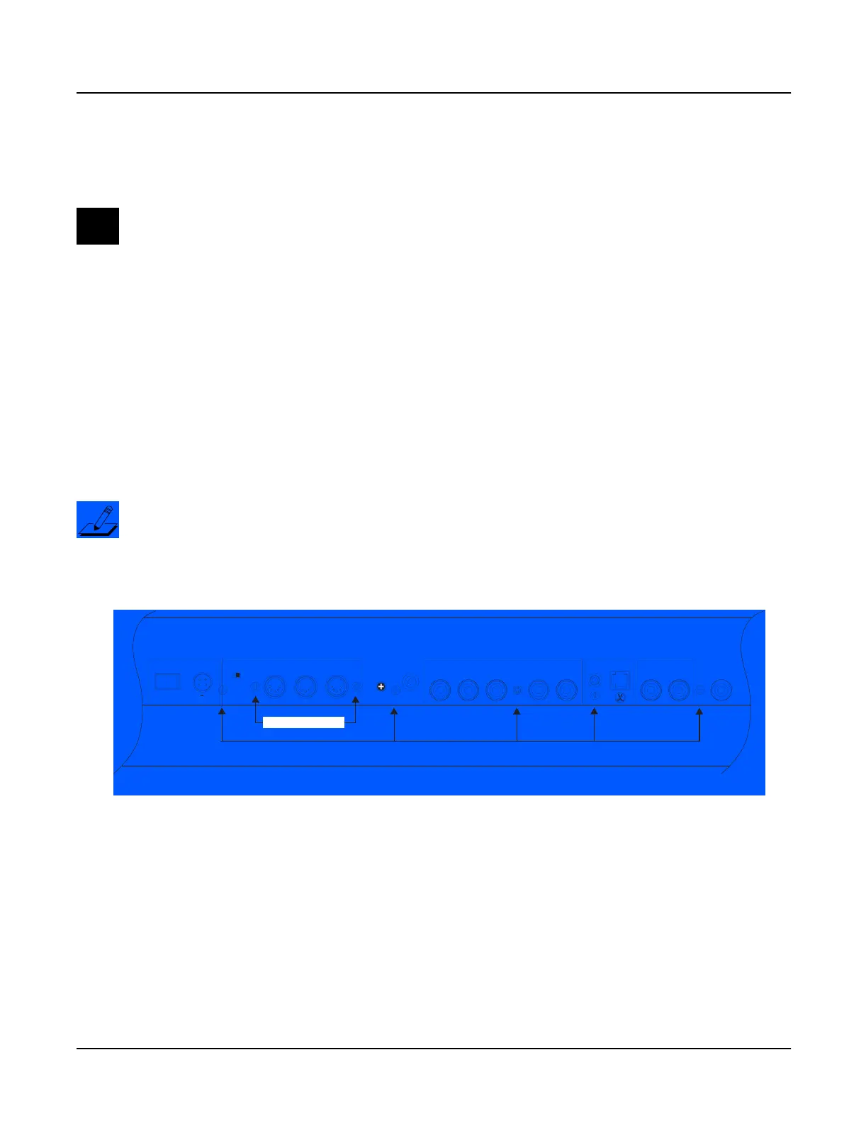
6. Remove the five screws that secure the Connector Board to the rear panel. Two of these
screws are longer than the others and have spacers located between the screw and the rear
panel. See Figure 4-7 for the locations of the screws and spacers.
Note: Do not remove any other hardware from this portion of the rear panel.
Figure 4-7 Rear panel hardware locations
7. Remove the two screws that secure the MIDI jacks to the rear panel. See Figure 4-7.
8. Remove the Connector Board.
Thru / Out
Thru / Out
In
Digital
Contrast
LCD
Out
Switch
Out
1
Continuous
132
Breath
2 Right
Ribbon
Left Headphones
Power MIDI Pedals Inputs Audio Outs
I / 0
Adapter In
9.0V 2.0A
14.0V~0.25A
longer screws with spacers
MIDI jack screws
*
**

 Loading...