4-16
PC2/PC2X Disassembly/Assembly
Top Enclosure
4. The flat ribbon cables connected to J403 and J412 use wire trap connectors. The shielding
has been removed from the end of these cables to expose the wires. The wires are inserted
directly into these connectors.
Lift up the sides of each connector. This unlocks the trap to free the cable wires. Gently
pull each cable up out of the connector. Note the marking (red or black) on each cable that
indicates the connection to Pin 1; you’ll need to reconnect the marked edge of the cable to
Pin 1 when you replace the Engine Board.
5. Disconnect the stranded wire cables from J402 and J405.
6. Remove the cable locking clip and disconnect the flat ribbon cable from J406. Be sure to set
the cable locking clip safely aside so that you can install it when you reconnect the cable.
7. Two of the screws that secure the left enclosure support wall also secure the front panel
edge of the Engine Board. You have already removed the enclosure support wall, but one
screw remains securing this edge of the board. See Figure 4-10, and remove the remaining
screw.
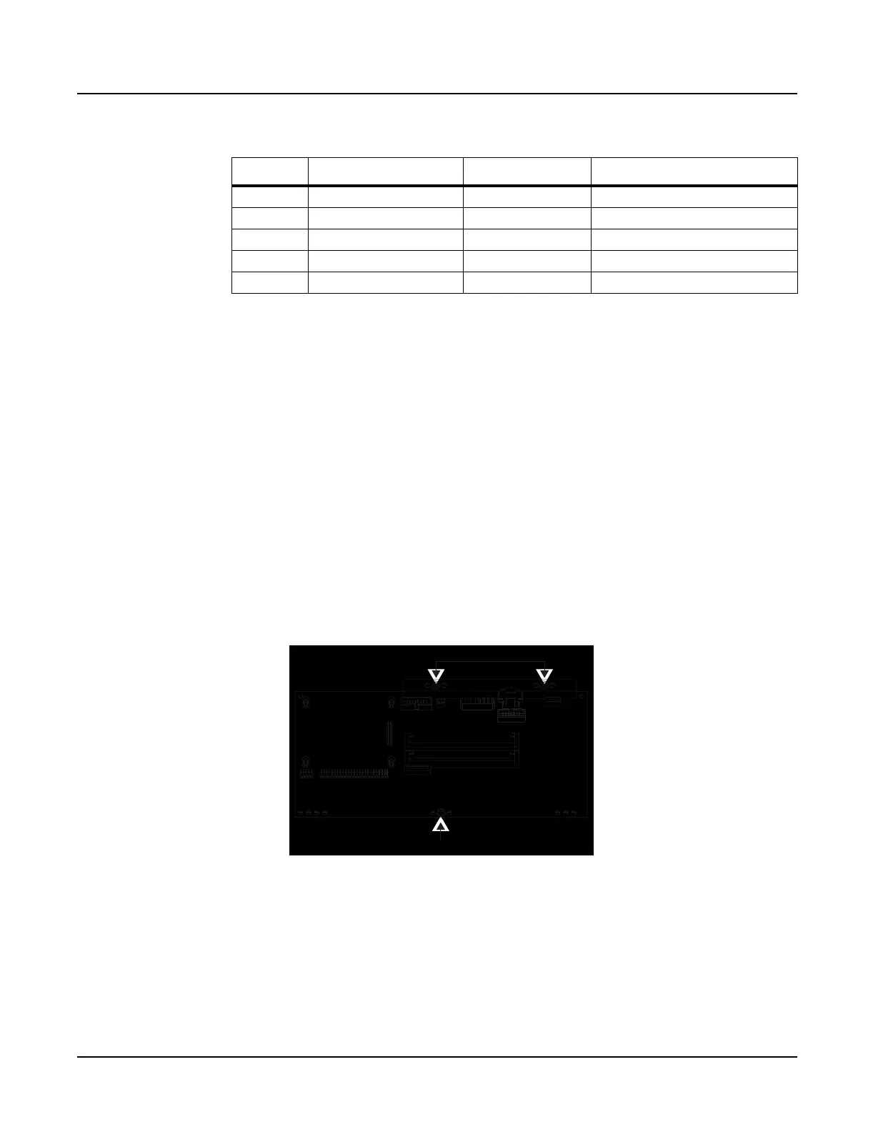
Figure 4-10 Engine Board, screw locations
8. Remove the two screws that secure the PC board clamp and rear panel edge of the Engine
Board to the top enclosure.
9. Remove the Engine Board.
Ref. Name Cable Type Destination
J402 PC2 PWR stranded wire Connector Board
J403 MIDI & CPU flat ribbon Connector Board
J405 Backlight stranded wire LCD Board
J406 LCD flat ribbon LCD Board
J412 PC2 Audio Out flat ribbon Connector Board
Table 4-4 Engine Board cables
PC board clamp and screws
Front panel edge screw
J412
J406
J405
J402
J403

 Loading...