Firmware ≤ 02.00 - DMS 2.1 EN - 03/2011 L 113
8400 motec | Software Manual
Motor control (MCTRL)
Braking operation/braking energy management
5.11.1 Settings for internal brake resistor E84DZEWxxxx
5.11.2 Voltage limits for braking operation
In case of the 8400 motec controller, the brake chopper is exclusively
switched on via a
hardware circuit.
For the braking methods C00175
= 2 / 4, the brake chopper threshold adjustable via
C00173
and C00174 is used in order to trigger the corresponding software response before
the brake chopper threshold on the hardware side is reached.
The braking method C00175
= 6 increases the motor magnetisation every time the
motor is decelerated. There is no reference to the DC-bus voltage.
The brake chopper threshold is preset as follows via the selected mains voltage
(C00173
):
This brake chopper threshold can be reduced by 0 ... 150 V by means of C00174
.
Example:
A 400 V device has a maximum mains voltage of 420 V AC.
Maximum stationary DC-bus voltage: 420 V AC * 1.414 = 594 V DC
This means that C00174
can be set to a maximum of 83 V DC (677 V DC - 594 V DC).
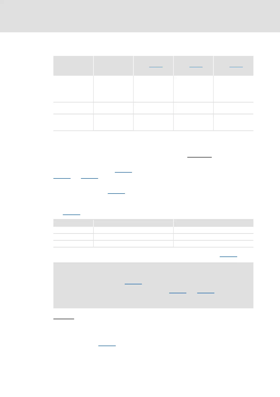
Resistance value
R
B
(C00129)
Rated power
P
D
(C00130)
Thermal capacity
Q
B
(C00131)
E84DGDVB... Brake resistor [Ω] [W] [kWs]
3714
5514
7514
1124
1524
E84DZEW220R 220.0 15 0.3
2224
3024
E84DZEW100R 100.0 15 0.3
4024
5524
7524
E84DZEW47R0 47.0 15 0.3
C00173 Mains voltage Brake chopper threshold
0 3-phase 400 V AC 677 V DC
1 3-phase 440 V AC 735 V DC
2 3-phase 480 V AC 775 V DC
Stop!
For the braking method C00175 = 2 / 4, the following applies:
The brake chopper threshold resulting from C00173
and C00174 must not
exceed the stabilised DC-bus voltage, since otherwise, deceleration cannot take
place!

 Loading...


