Indoor unit
No. setting
Group number 0
On central control
Indoor unit number 1
On central control
Group unit
No. setting
Rotary_low
Rotary_low
Rotary_high
Rotary_high
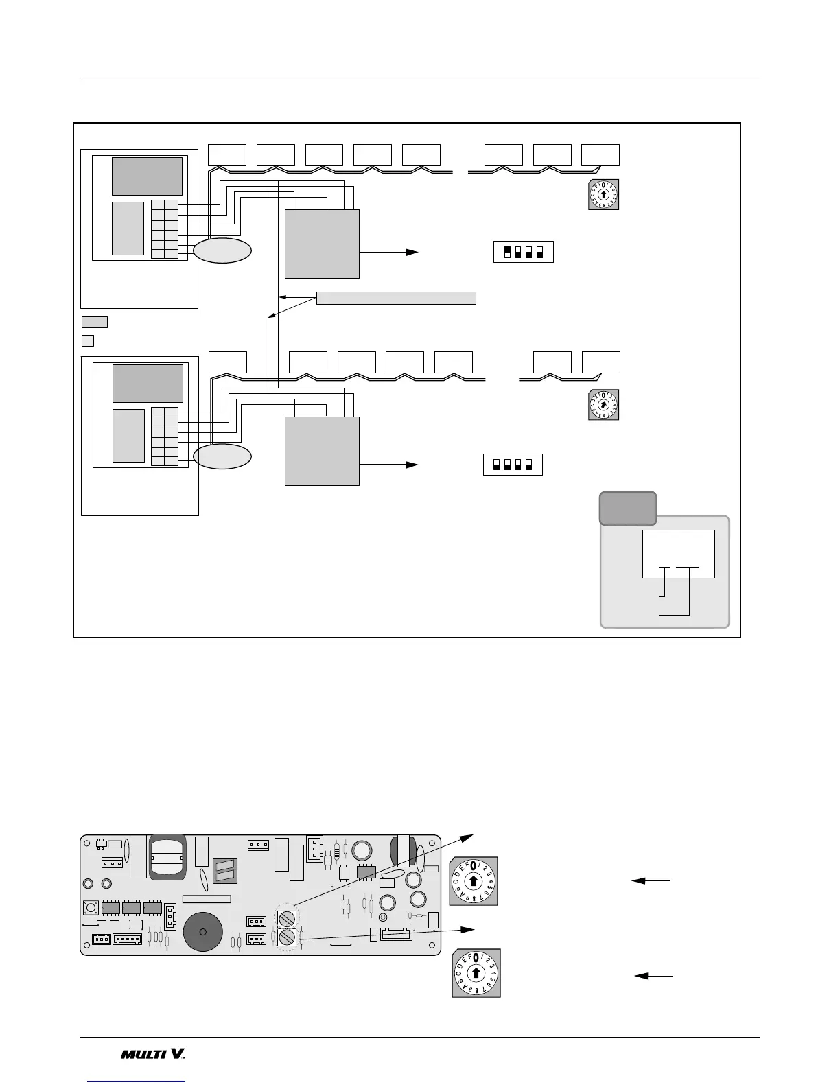
The indoor unit PCB has 2 rotary switches. One is for the Group Number setting and another is for Room
Number Setting. The group number on the Central Control rotary switch and on the rotary switch of Indoor
Unit PCB should match exactly.
Like: Group Number 0 on the Central Control = Group Number 0 on all Indoor units to be connected to Group
Number 0.
But the Room Number switch on Central control is one increment of the rotary switch
number on the Indoor PCB.
Like: Rotary switch number 0 on the indoor unit PCB means Room number 1 on the
central control.
Outdoor unit
Outdoor unit
Outdoor unit
Outdoor unit
Indoor unit
MAIN PCB
SUB
C
D
VCC
A
B
GND
C
D
A
B
VCC
GND
C
D
VCC
A
B
GND
C
D
A
B
VCC
GND
To Indoor
Units
<Group Number 0>
103 104 105 115 116102101
MAIN PCB
SUB
<Group Number 1>
The connection of Master and Slave
Master
Slave
: SUB PCB
T.B : TERMINAL BLOCK
SUB
Central
control
Unit 1
GNDVcc DC
Central
control
Unit 1
GNDVcc DC
DIP SWITCH
DIP SWITCH
003 004 005
...
...
014 015 016002001
To Indoor
Units
Indoor unit
Indoor unit
Indoor unit
001
Group No.
Indoor No.
Note
1. Adhere the 485 SUB PCB(For connecting central control) to the Control Box.
2. Connect the 485 SUB PCB to central control.
3. In the case of connecting two more than central control, set the Master/Slave mode
and then connect each communication lines(C,D) <Refer to above fig>.
*Special purcharse: Central control(P/No.:4995A20105F),
Sub PCB(P/No.:4995A20105G)
* It can be added to 15 Central controls for the slave control.
 Loading...


