Indoor unit
Indoor unit
Outdoor unit
Outdoor unit
Outdoor unit
Outdoor unit
Group Number 0
Master Mode
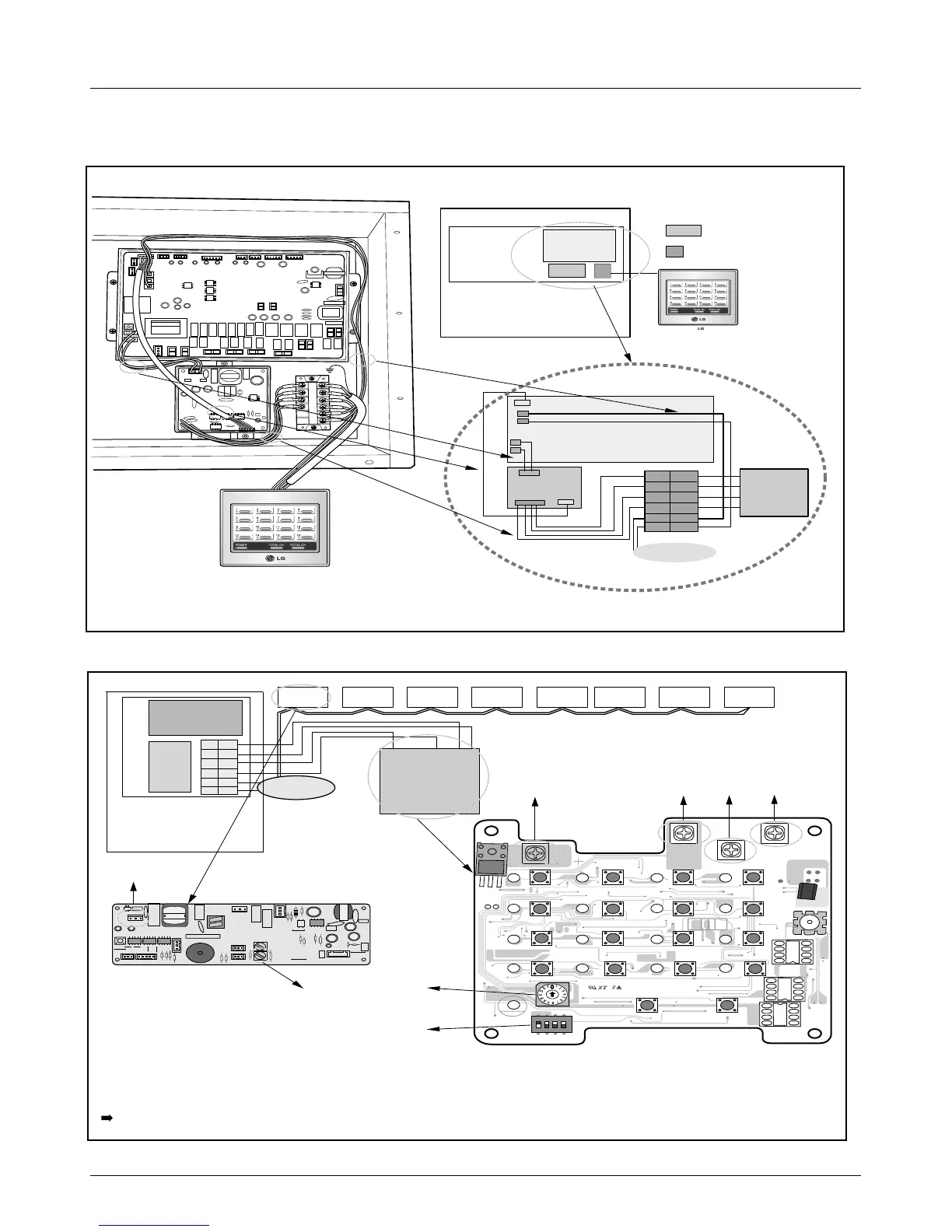
All the connections are to be done as shown above.
A and B are the communication lines for the indoor and
C and D are the communication lines for the Central Control.
Use two shield lines for C/D connecting line.(Earth the shield line)
• Special purcharse: Central control, Sub(485-Gateway)
Vcc
GND
C
D
A, B(Communication Line)
MAIN PCB
SUB
C
D
VCC
A
B
GND
C
D
A
B
VCC
GND
To Indoor
Units
<Group Number 0 >
Central
control
Unit 1
GNDVcc DC
003 004 005 006 007 008002001
CN-POWER
GND
CN-COM A
S4
S3
S12
S16
TX1
LED4
LED8
LED12
LED11
LED16
LED15
PWB:6870A10001A
ASM:6711A20005E
LED7
LED3
L
+
+
+
+
+
+
+
+
+
S15
S18
S19
S15
S11
S2
LED2
S5
S9
+
+
+
S1
IC1P
LED5
LED9
LED13
LED17
LED10
LED14
S14
+
S6
S10
CN-POWER
CN-COM B
ON
L1 2 3 4
KSDO4H
T.B
SUB : SUB PCB
: TERMINAL BLOCK
SUB PCB
C
D
VCC
A
T.B
Control
Earth Shield Line
JIG1
JIG2
To Indoor unit
MAIN PCB
CENTRAL
CONTROL
UNIT
MAIN PCB
SUB
T.B
Control Box
GND
C
D
VCC
B
GND
A
B
A
VCC
B
GND
C
D
To Indoor
Units
 Loading...


