• Group number of each indoor unit is set with rotary switch of control PCB in each indoor unit
• Before power is supplied the rotary switch for simple central controller on the indoor unit PCB should be set
• ID Mapping of Rotary Switch is following table
3.3.1 Process fot Group Number Setting
➀ Confirm the power of whole system(indoor unit, outdoor unit) is OFF, otherwise turn off.
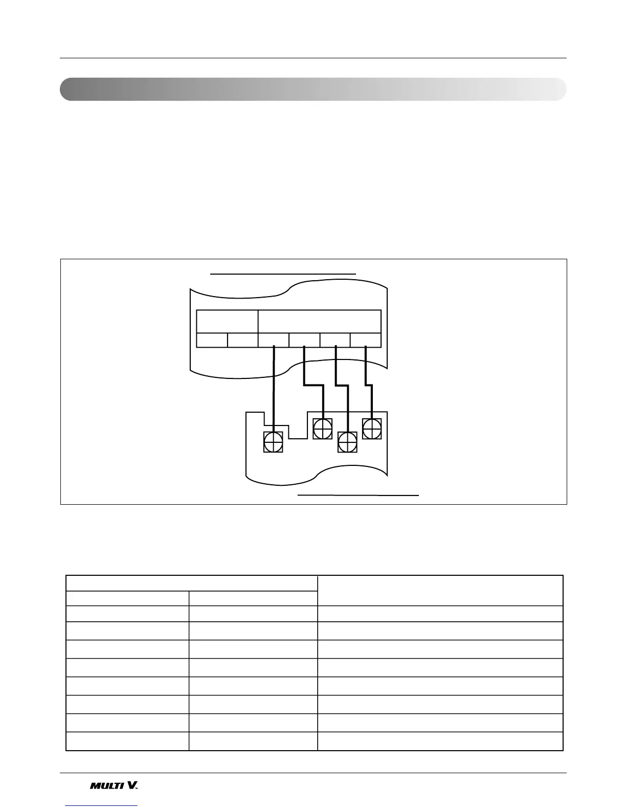
➁ The transmission lines connected to C, D of simple central controller should be connected to C,D terminal port
for central control of outdoor unit with care for their polarity (C ➔ C, D ➔ D)
➂ DC power line(12V) and ground line should be connected to terminal block of adjacent indoor unit
➃ Set group number with increasing the rotary switch From 00 to 7F in orderly manner (if it is desired to control
several indoor units as a group, each group control is possible by group ID rotary switch setting from 0 to 7)
➄ The whole system power turn on.
3.3 Group number setting for indoor units
 Loading...


