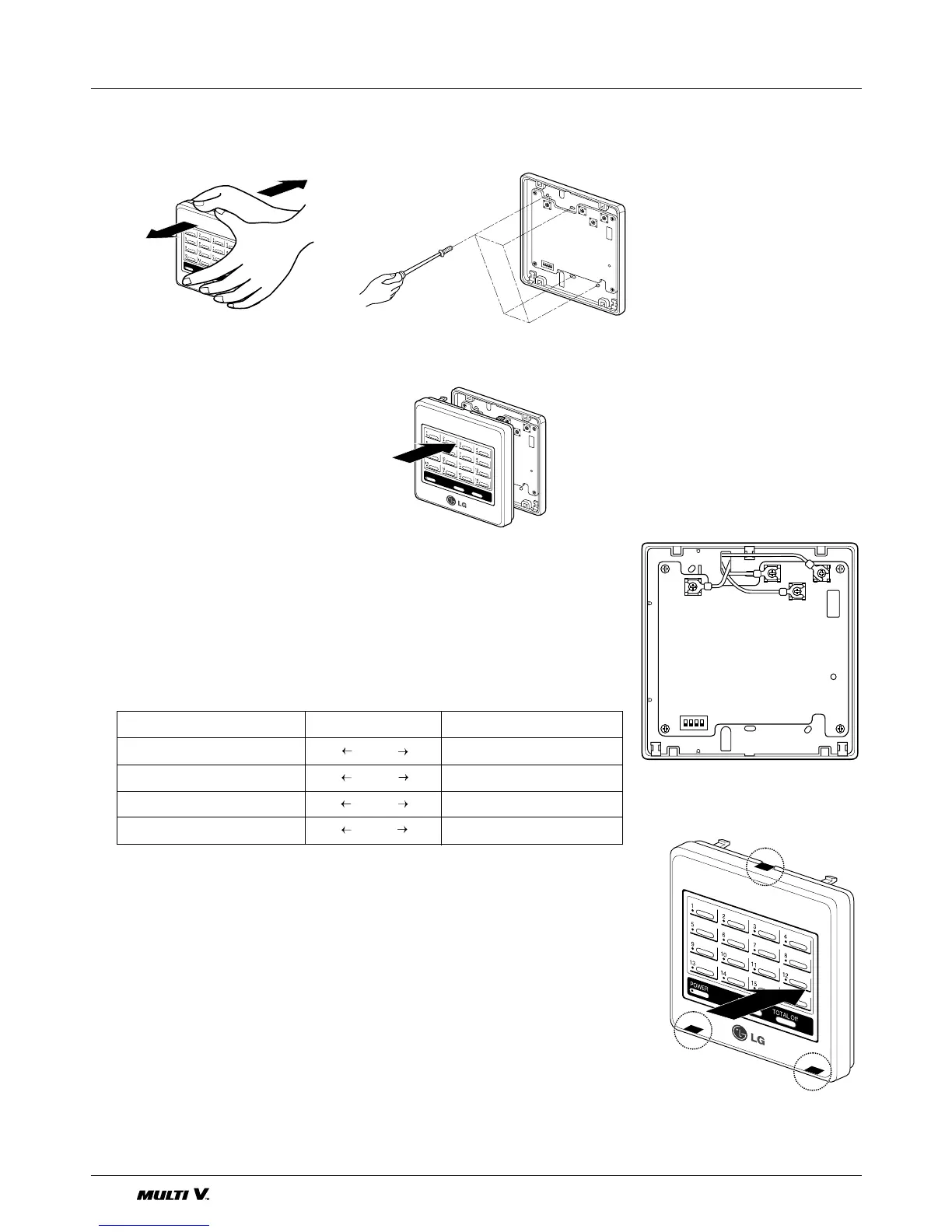
■ INSTALLATION ORDER
■ LINK OF CONNECTING WIRE
1. First, separate the front case from rear case of controller, connect terminal
C, D,Vcc, GND on PCB referring to the following table.
Maximum length of connecting wire
• Between controller and outdoor unit : 220m(25Ω )
• Between controllers : 220m(25Ω )
2. After attaching the supplied wire to terminal, link the connecting wire.
If necessary, Cut the indicated part of front case to draw the lead wire.
1. Remove upper & lower case. 2. Fixate screw in the holes of the
case bottom.
3. For Dip switch, and Rotary
switch setting, refer to the page
“How to Install”.
4. For wiring connection, refer page
“Installation Procedure”
5. Adjust the upper case in accor-
dance with back case while
assembling as shown in the fig-
ure.
6. Check the operation by supply-
ing the power.
 Loading...


