215585 143 Revision A
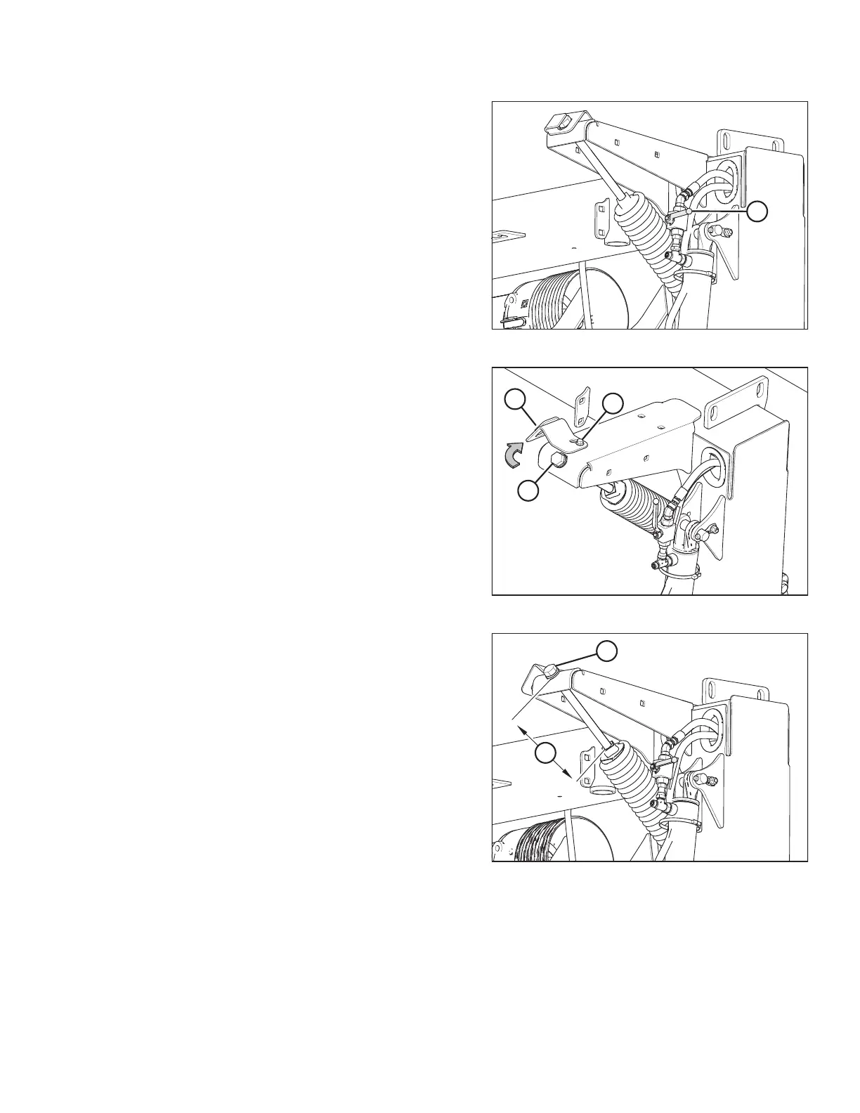
Figure 8.11: Cylinder Lock-Out Valve – Closed Position
4. Close the rotary disc pull-type’s lift cylinder lock-out
valve (A) on each lift cylinder by turning the handle to the
horizontal position (90° to the hose). Repeat on
opposite side.
Figure 8.12: Float Spring – Right Side
5. Loosen retaining bolt (A) and rotate cover plate (B) away
from float spring bolt (C). Repeat on opposite side.
6. Fully loosen float spring bolt (C). Repeat on opposite side.
Figure 8.13: Adjuster Bolt
7. Turn adjuster bolt (A) to achieve the recommended
measurement (B) for the conditioner type. Refer to
Table 8.1, page 144 for measurements.
NOTE:
Float settings indicated in the table are starting points only.
Float force should still be checked with the rotary disc pull-
type float and cutting angle set as planned for use in
the field.
• Turn bolt clockwise (towards spring) to increase float.
• Turn bolt counterclockwise (away from spring) to
decrease float.
Repeat on opposite side.
PERFORMING PREDELIVERY CHECKS