215585 43 Revision A
Figure 3.86: Alignment Control – Rear Right View
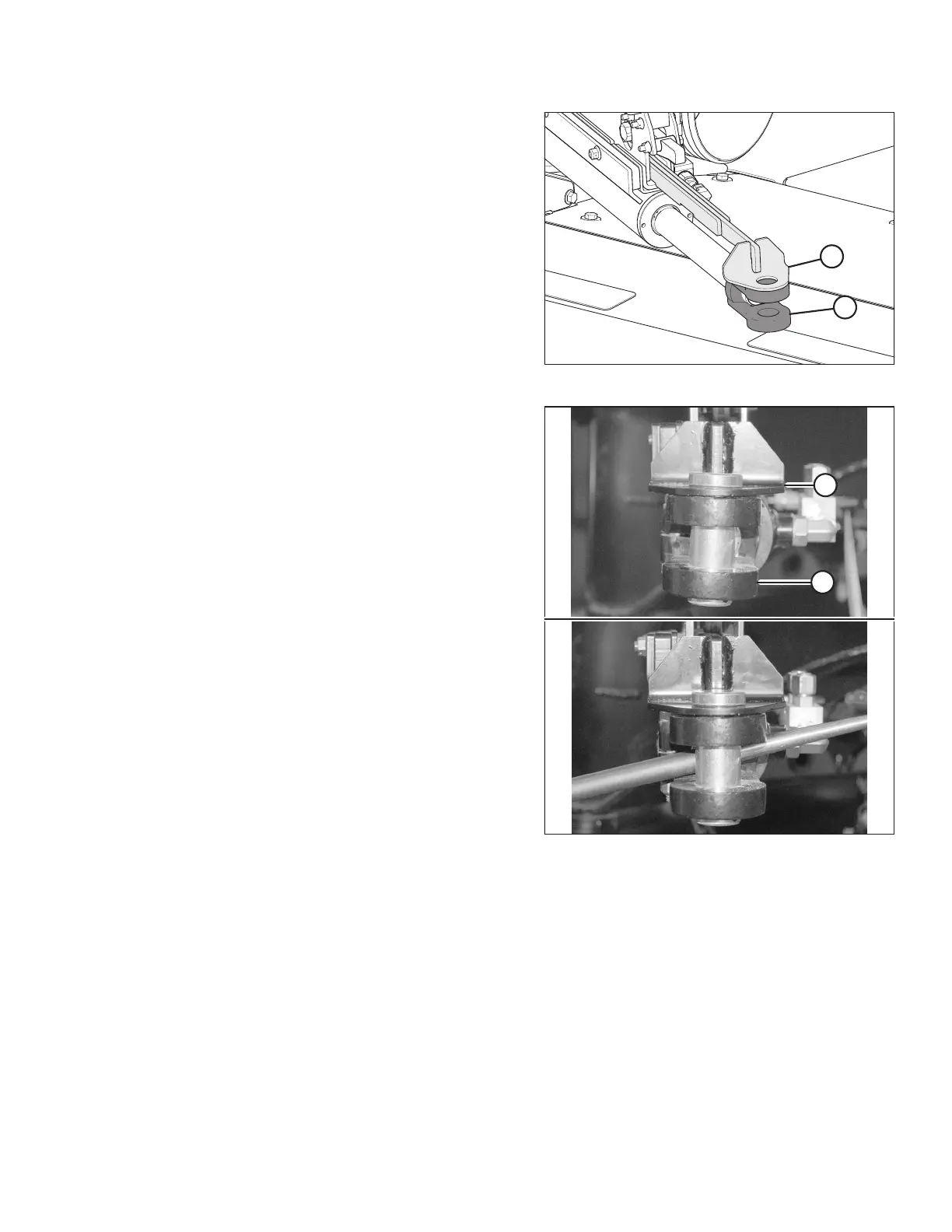
5. Align hole in cam arm (A) with hole in clevis (B) on the rod
end of the cylinder.
Figure 3.87: Cam Arm Alignment
6. Ensure the end of cam arm (A) is parallel with clevis (B) on
the rod end of the cylinder. If adjustment is required, use a
bar to turn the clevis until the clevis is parallel with
cam arm (A).
NOTE:
The rod end of the cylinder will be attached to the
transport casting after the system is primed. For
instructions, refer to 6.2 Priming the Hitch Swing Cylinder,
page 111.
ASSEMBLING THE ROTARY DISC PULL-TYPE – WITH OR WITHOUT THE DEALER-INSTALLED TRANSPORT